Signal coupling device

a signal coupling and signal technology, applied in the direction of powerline communication systems, electrical controllers, electrical apparatus, etc., can solve the problems of difficult to achieve perfect symmetry of configurations, difficult to achieve shielding of magnetic field by the outer shield portion, interfering electric waves to be exerted on wireless equipment, etc., to reduce the influence of electromagnetic compatibility (emc) or the like on surrounding wireless equipment, and reduce the leakage of magnetic field

Inactive Publication Date: 2007-01-11
MITSUBISHI ELECTRIC CORP
View PDF2 Cites 6 Cited by
  • Summary
  • Abstract
  • Description
  • Claims
  • Application Information

AI Technical Summary

Benefits of technology

[0008] The present invention has been made with a view to solving the above-mentioned problems, and therefore it is an object of the present invention to provide a signal coupling device with which the leakage of magnetic field from a signal line connecting between a PLC modem and a signal coupling device to the outside thereof is suppressed to thereby reduce the influence of such magnetic field leakage on wireless equipment located in the vicinity of the signal line.
[0010] Since the signal coupling device according to the present invention includes: the signal coupling member having a hollow portion through which the power line penetrates; and the signal line covered with an insulating coating, the signal line having the penetrating portion that penetrates through the hollow portion, and the first transmission portion and the second transmission portion extending from the penetrating portion and being arranged at a predetermined spacing from each other, the magnetic field intensity at a position distant from the first transmission portion and the second transmission portion is thus extremely small due to the canceling of magnetic fields. Accordingly, it is possible to reduce leakage of magnetic field to the outside of the region including the first transmission portion, the second transmission portion, and the space therebetween, whereby the influence of Electromagnetic Compatibility (EMC) or the like on surrounding wireless equipment can be reduced.

Problems solved by technology

However, it is difficult to achieve perfect symmetry of the configurations of the central conductor and outer covering shield portion, which makes it difficult to achieve shielding of magnetic field by the outer shield portion.
Since power line communication uses, for example, a high-frequency signal whose frequency falls within a 2 to 30 MHz band or KHz band, a magnetic field leaking to the outside of the signal coupling device causes interfering electric waves to be exerted on wireless equipment located in the vicinity of the signal coupling device.
When, in order to overcome this problem, the output of the PLC modem is lowered to thereby reduce the magnetic field leakage from the signal line connecting between the signal coupling device and the PLC modem, the strength of the PLC signal weakens so the range of possible PLC communication becomes narrow.

Method used


Image

  • Signal coupling device
  • Signal coupling device
  • Signal coupling device

Examples


embodiment 1

[0027] Hereinbelow, a signal coupling device according to Embodiment 1 of the present invention will be described with reference to the drawings.

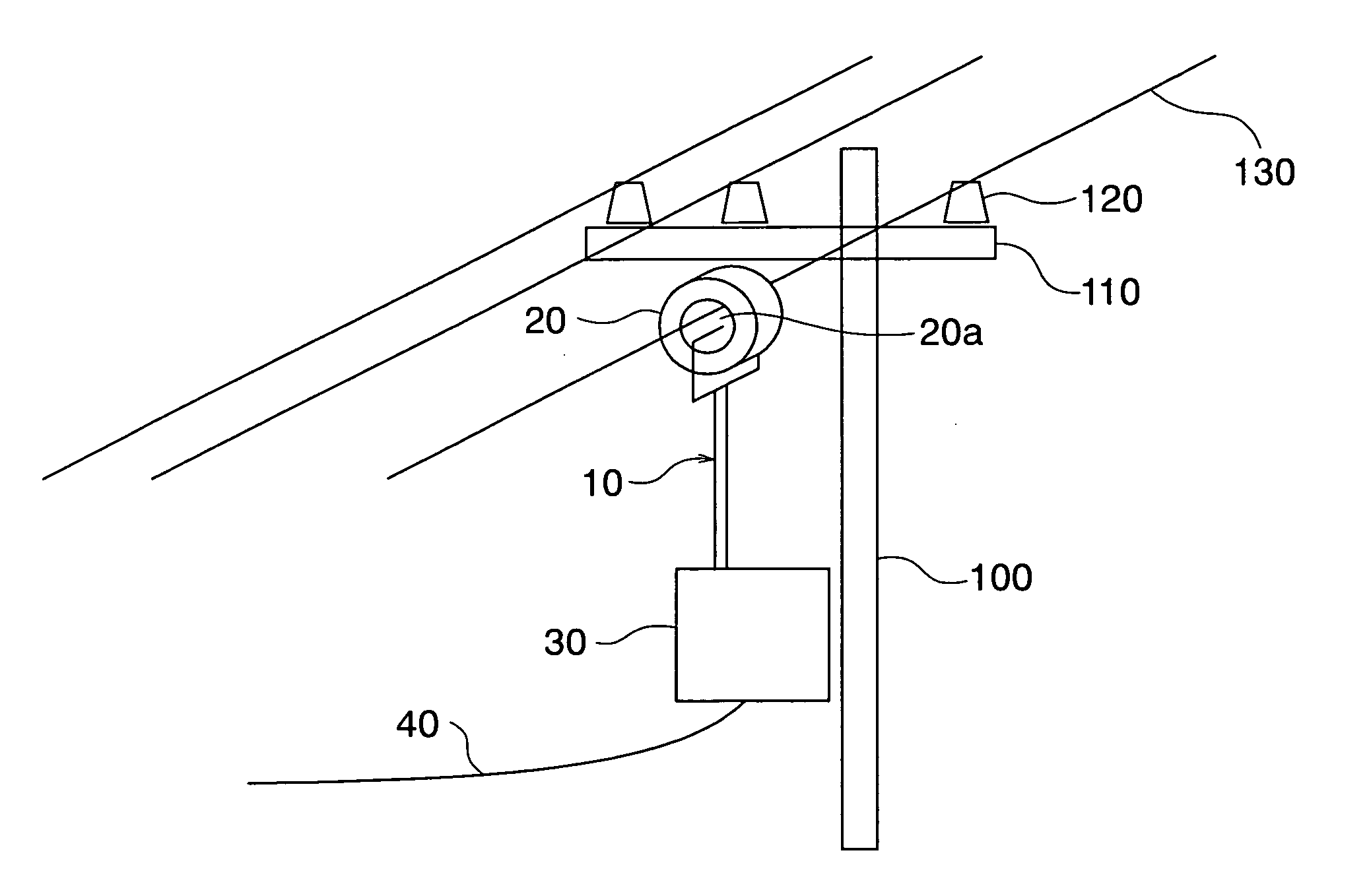
[0028]FIG. 1 is a diagram showing a state where a PLC modem is connected to the signal coupling device according to Embodiment 1 of the present invention.

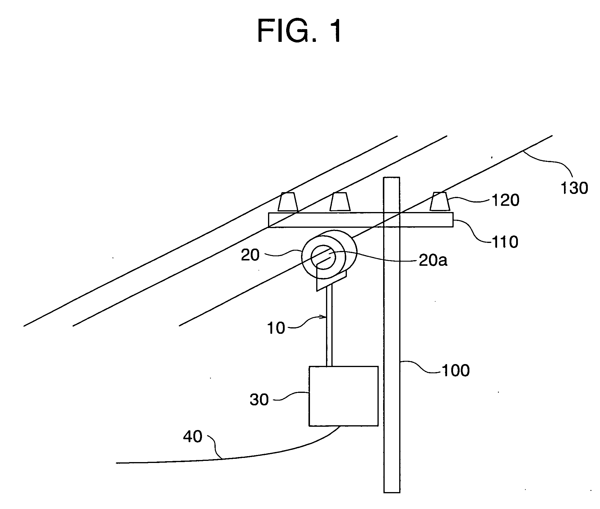
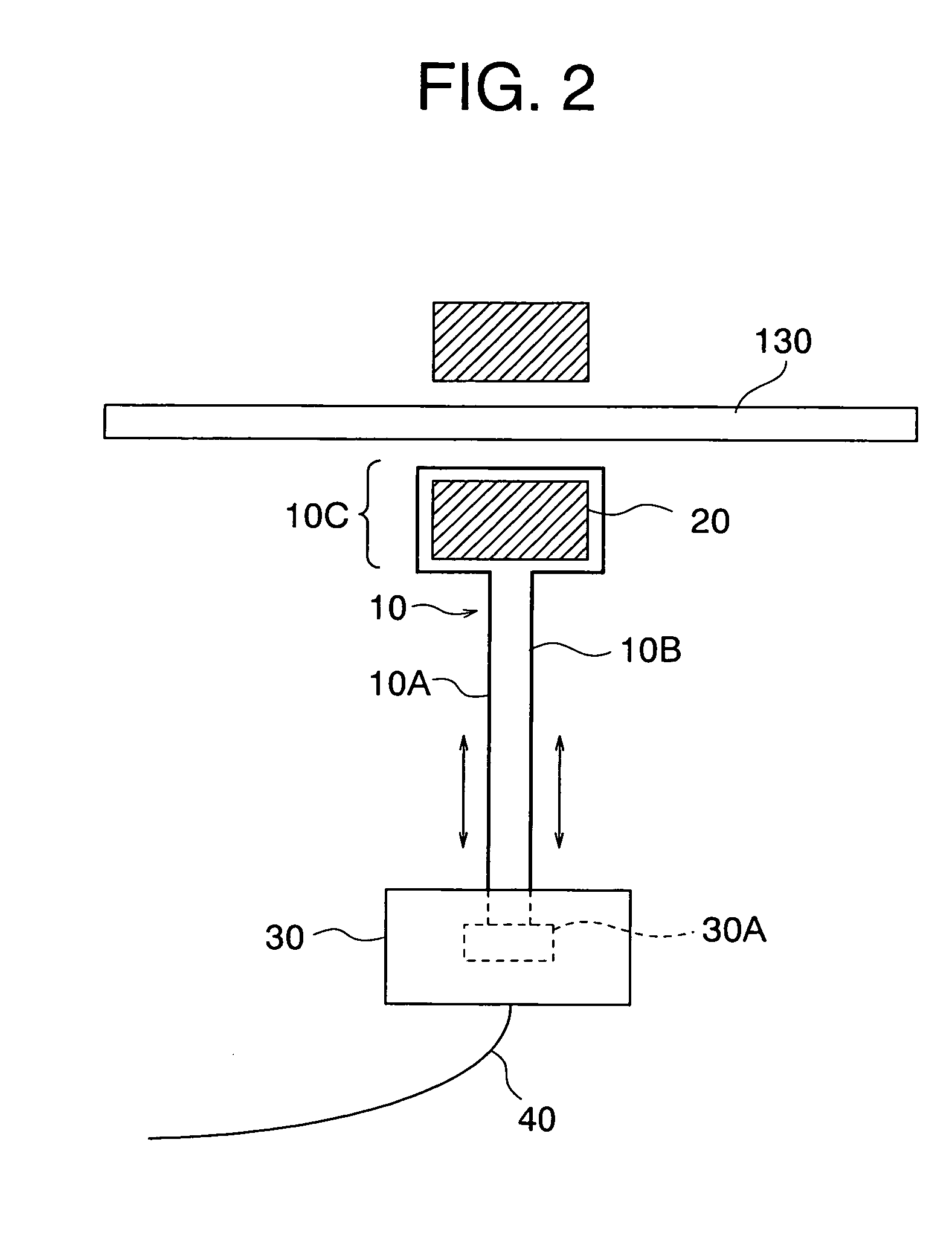
[0029]FIG. 2 is a diagram showing the wiring structure of a PLC signal line in the signal coupling device according to Embodiment 1 of the present invention, together with the sectional structures of the signal coupling device and power line.

[0030] As shown in FIG. 1, the signal coupling device according to Embodiment 1 of the present invention is an inductive coupling unit including an inductive coupling member 20 and a PLC signal line 10 for transferring a PLC signal between a power line 130 and a PLC modem 30.

[0031] Further, a plurality of power lines 130 are suspended from a power pole 100 through support insulators 120.

[0032] The signal coupling member 20 is an annular member hav...

embodiment 2

[0046]FIG. 4 is a diagram showing the wiring structure of a PLC signal line in a signal coupling device according to Embodiment 2 of the present invention, together with the sectional structures of the signal coupling device and power line.

[0047]FIG. 5 is a diagram conceptually illustrating magnetic fields generated by the PLC signal line of the signal coupling device according to Embodiment 2 of the present invention. FIG. 5 shows the magnetic fields as generated when the directions of currents flowing in the first transmission portion 10A and in the second transmission portion 10B upon transmission of a PLC signal are as indicated by the arrows A and B, respectively.

[0048] The construction of the signal coupling device according to Embodiment 2 is similar to that of the signal coupling device according to Embodiment 1 except for the wiring structure of the PLC signal line 10.

[0049] As shown in FIG. 4, the first transmission portion 10A and second transmission portions 10B of th...

embodiment 3

[0052]FIG. 6 is a diagram showing the wiring structure of a PLC signal line in a signal coupling device according to Embodiment 3 of the present invention, together with the sectional structures of the signal coupling device and power line.

[0053] As shown in FIG. 6, the signal coupling device according to Embodiment 3 of the present invention includes a magnetic shield 50 covering the two parallel transmission portions, the first transmission portion 10A and the second transmission portion 10B. The opposite ends of the magnetic shield 50 are connected by connecting wires 60 and 70 to a ground wire 310 installed in a power distribution pole 100.

[0054] By covering the first transmission portion 10A and the second transmission portion 10B with the magnetic shield 50 that is grounded, it is possible to reduce the amount of magnetic fields leakage to the exterior without being canceled out between the first transmission portion 10A and the second transmission portion 10B extending para...


PUM


Abstract

Provided is a signal coupling device which suppresses the leakage of magnetic field to the outside from a signal line connecting between a PLC modem and the signal coupling device, thereby reducing the influence of such magnetic field leakage on wireless equipment in the vicinity thereof. The signal coupling device includes: a signal coupling member having a hollow portion through which a power line penetrates; and a signal line covered with an insulating coating, the signal line having a penetrating portion penetrating through the hollow portion, and a first transmission portion and a second transmission portion which connect the opposite ends of the penetrating portion to the modem to thereby transmit a PLC signal. The first transmission portion and the second transmission portion are arranged not coaxially but at a predetermined spacing from each other.

Description

BACKGROUND OF THE INVENTION [0001] 1. Field of the Invention [0002] The present invention relates to a signal coupling device for coupling a high-frequency signal for power line communication (PLC) to an electric circuit. [0003] 2. Description of the Related Art [0004] For the power line communication as described above, there is used a modem for power line communication (hereinafter referred to as “PLC modem”). In conventional signal coupling devices, the PLC modem and the signal coupling device are connected to each other by a coaxial cable, and a PLC signal is bidirectionally transferred between a power line and the modem (refer to, for example, JP 10-504948 A). [0005] In conventional signal coupling devices, a magnetic field is induced in the outer shield portion of a coaxial feed line by means of an electric current flowing in a direction opposite to the direction of a signal in a central portion of a coaxial signal line, so a signal passing through the central conductor of the...

Claims


Application Information

Patent Timeline
Patent Type & Authority Applications(United States)
IPC IPC(8): G05B11/01
CPCH04B2203/5483H04B3/56
Inventor SHIMOMURA, TETSURO
Owner MITSUBISHI ELECTRIC CORP
Why Eureka
Try Eureka