Optical disk device

a technology of optical disk drive and optical disk drive, which is applied in the field of optical disk drive, can solve the problems of prone to faint movement, and achieve the effect of high-reliability optical disk driv

Inactive Publication Date: 2007-01-11
HITACHI LTD +1
View PDF0 Cites 14 Cited by
  • Summary
  • Abstract
  • Description
  • Claims
  • Application Information

AI Technical Summary

Benefits of technology

[0006] However, the aberration-correcting movable lens is required to have an ability to firmly hold its position once fixed in the optical-axis direction, or retainability without being affected by the external vibration or the like.
[0008] Thus, it is an objective of the invention to provide an optical disk drive capable of solving the above problems and of highly reliable operation.
[0010] According to this invention, it is possible to provide a highly reliable optical disk drive.

Problems solved by technology

In addition, the movable lens has a problem that it is apt to faintly move in the direction perpendicular to the optical axis or to have a tilt to the optical axis due to the looseness between the movable portion and the drive shaft.

Method used


Image

  • Optical disk device
  • Optical disk device
  • Optical disk device

Examples


embodiment 1

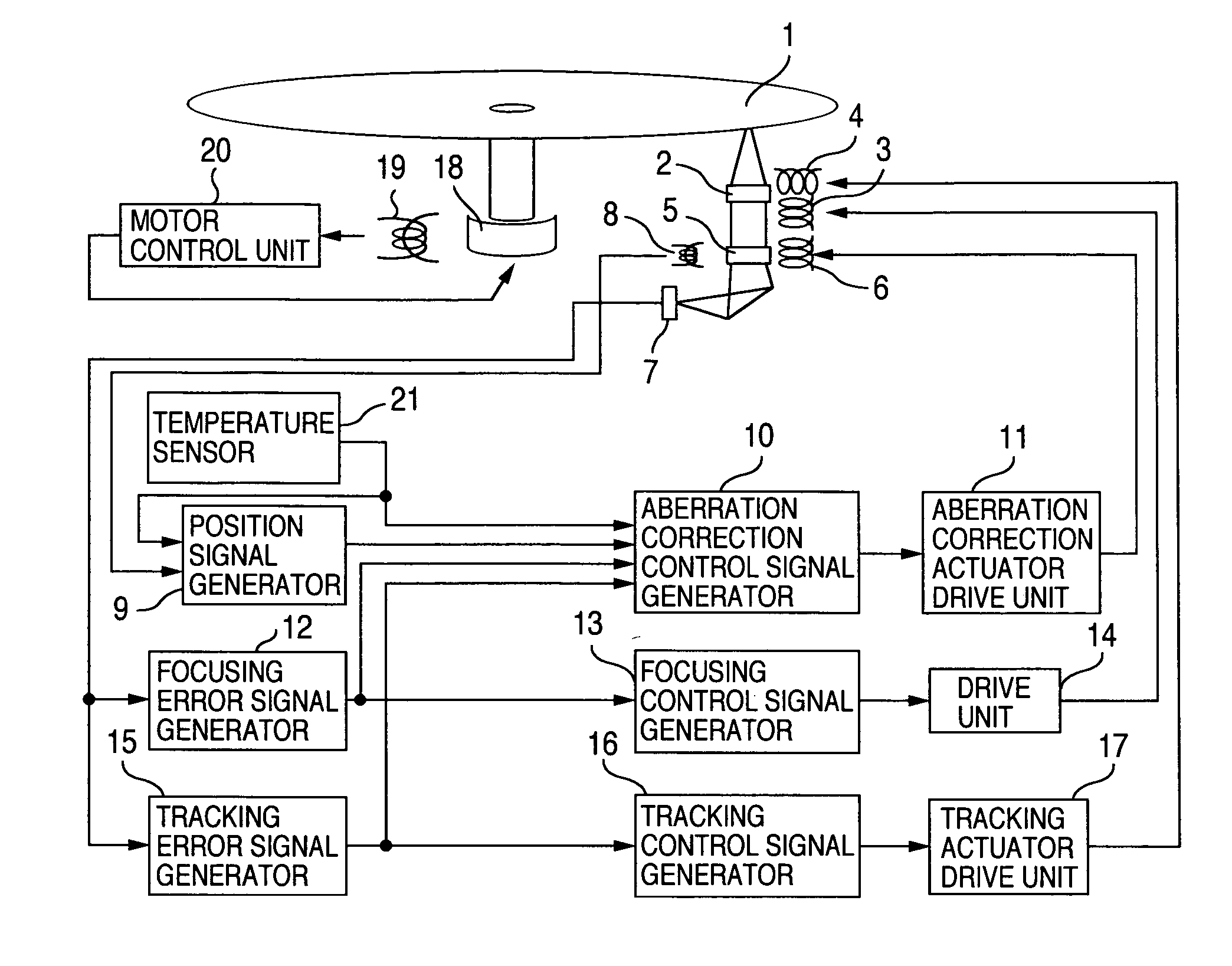
[0026] The construction of an optical disk drive of the invention will be described first with reference to FIGS. 1 and 2.

[0027] Referring to FIG. 1, there are shown a disk 1 for recording / reproducing data, an objective lens 2 for use in gathering beam flux on the disk 1, a focusing actuator 3 to drive the objective lens 2 in the rotation-axis direction of the disk 1, a tracking actuator 4 to drive the objective lens 2 in the radius direction of the disk 2, an aberration correcting lens 5 for correcting the aberrations and an aberration correcting actuator 6 to drive the aberration correcting lens 5 in the optical-axis direction. In addition, there are shown an optical detector 7 for optically detecting the disk 1, a position detector 8 for detecting the position of the aberration correcting lens, a position signal generator 9 for setting the operating point and sensitivity relative to the output from the position detector 8, and an aberration correction control signal generator 10...

embodiment 2

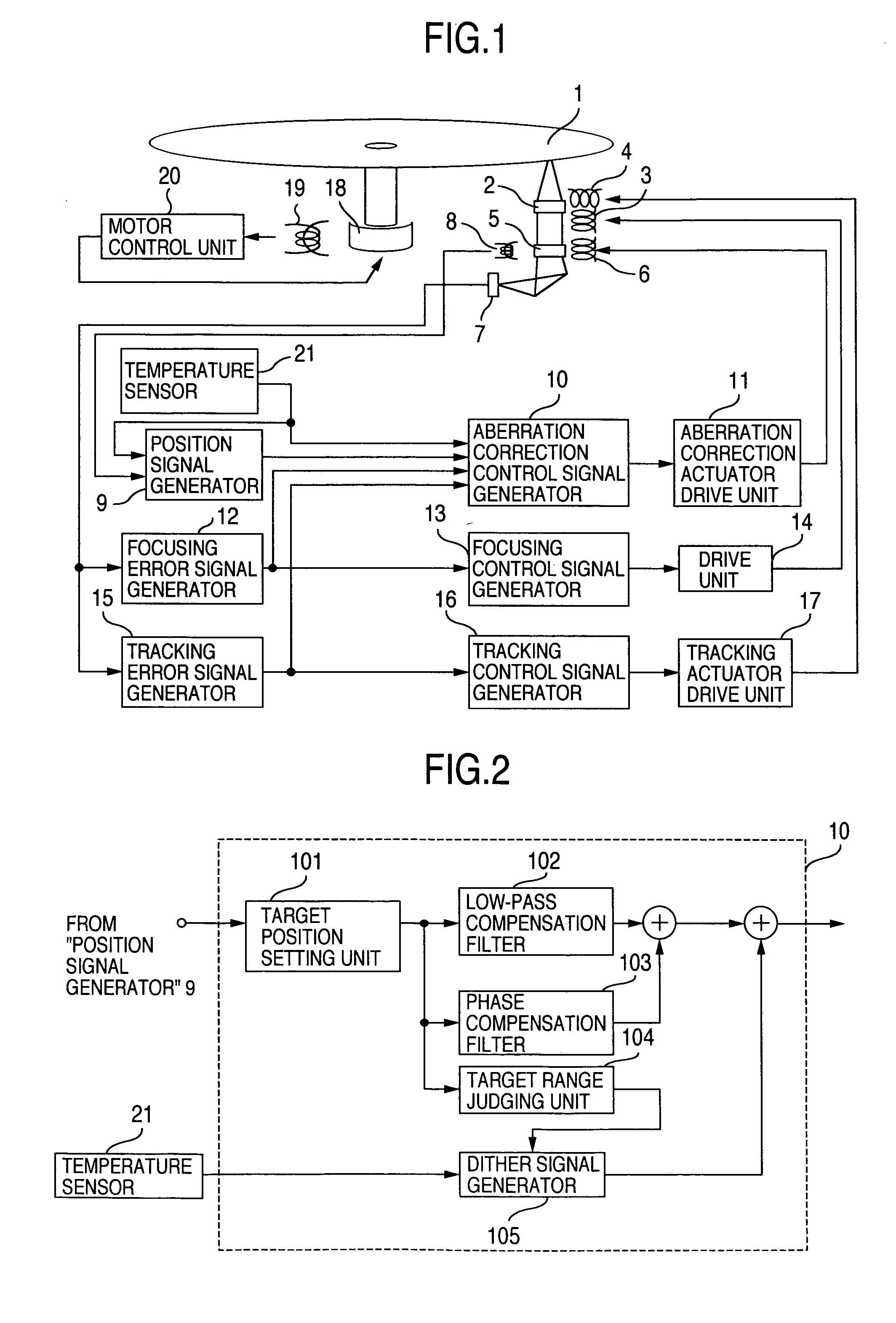
[0051] The construction of the optical disk drive of the invention will be described with reference to FIGS. 1 and 3.

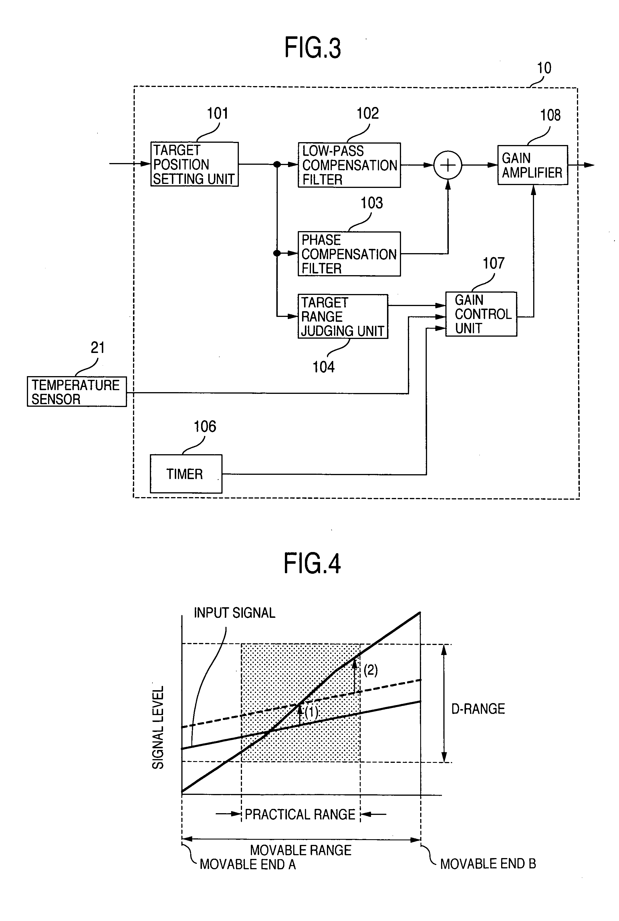
[0052] In the embodiment 2, the blocks 1 through 21 shown in FIG. 1 are the same as in embodiment 1, and thus will not be described. FIG. 3 is a block diagram of the aberration correction control signal generator 10 of the embodiment 2. The blocks 101 through 104 shown in FIG. 3 are the same as in embodiment 1, and thus will not be described. In FIG. 3, there are shown a timer 106, a gain control unit 107 for the aberration correction control, and a gain amplifier 108 of the aberration correction control loop.

[0053] The outline of the operation of each block and the relation between the blocks will be described.

[0054] The focusing control, tracking control and spindle control are the same as in embodiment 1, and thus will not be described. The aberration correcting actuator 6 moves the aberration correcting lens 5 in the optical-axis direction. The aberration-corre...

embodiment 3

[0060] The flowchart of a specific control in embodiment 1 will be described with reference to FIGS. 13 and 14.

[0061] First, referring to FIG. 13, when the aberration correcting element needs to be driven with the focusing control on and with the tracking control off, condition setting is first performed in order to suppress the effect of the superposition of high-frequency signal and the drive signal for the aberration correcting element on the focusing control. At this time, the condition setting is made so that the focusing error signal can be observed when the focusing control and tracking control are both turned off. In addition, the high-frequency signal is not applied.

[0062] Then, the focusing error signal amplitude is acquired under the condition that the high-frequency signal is not applied (S11). This value is represented by Fe0.

[0063] Next, the dither signal (high-frequency signal) is added to the drive signal for the aberration correcting element (S12). At this time, ...


PUM

PropertyMeasurementUnit
frequencyaaaaaaaaaa
constant timeaaaaaaaaaa
timeaaaaaaaaaa

Abstract

An optical disk drive having a laser source for irradiating an optical beam onto an optical disk, a lens unit to focus the optical beam from the laser source onto the optical disk, a drive unit for driving the lens unit, and a high-frequency signal output unit for producing a high-frequency signal. The drive unit drives the lens unit by applying the high-frequency signal before the optical disk is started to reproduce, and drives it without applying the high-frequency signal after the optical disk is started to reproduce. Thus, it is possible to effectively control the aberration correction mechanism using a linear actuator.

Description

INCORPORATION BY REFERENCE [0001] The present application claims priority from Japanese application JP2005-181403 filed on Jun. 22, 2005, the content of which is hereby incorporated by reference into this application. BACKGROUND OF THE INVENTION [0002] The present invention relates to an optical disk drive that reproduces optical disks [0003] Until now, a technique is proposed of a closed loop control using a movable lens and a position sensor for the way the aberrations in the optical disk drive are corrected as disclosed in, for example, JP-A-2002-352449. [0004] In addition, another technique for the aberration correction method has been offered in which the closed loop control is made by computing the amount of correction from the movable lens and reproduced signals with long and short periods as described in, for example, JP-A-2004-241102. SUMMARY OF THE INVENTION [0005] As described in the above patent documents, an approach is employed to drive the aberration-correction movabl...

Claims


Application Information

Patent Timeline
Patent Type & Authority Applications(United States)
IPC IPC(8): G11B7/00
CPCG11B7/13925
Inventor IMAGAWA, SEIJISUZUKI, MOTOYUKIFUKUSHIMA, AKIO
Owner HITACHI LTD
Why Eureka
Try Eureka