Redundant pseudowires between Ethernet access domains

a pseudo-wire and ethernet access technology, applied in the field of digital computer network technology, can solve problems such as single point of failure in network connection installation, redundancy problem, and difficult implementation of approach,

Active Publication Date: 2007-01-11
CISCO TECH INC
View PDF83 Cites 119 Cited by
  • Summary
  • Abstract
  • Description
  • Claims
  • Application Information

AI Technical Summary

Problems solved by technology

A particular redundancy problem arises when Ethernet and STP are combined with pseudowires.
One possible solution to this problem is to devise a mechanism for running STP over pseudowires; however, this approach is considered too unwieldy and difficult to implement.
The primary drawback of this latter approach is that it means that it installs a single point of failure in network connections.
Thus, there is an unsatisfied need for alternative network architectures and topologies that overcomes the shortcomings of the prior art.

Method used


Image

  • Redundant pseudowires between Ethernet access domains
  • Redundant pseudowires between Ethernet access domains
  • Redundant pseudowires between Ethernet access domains

Examples


Embodiment Construction

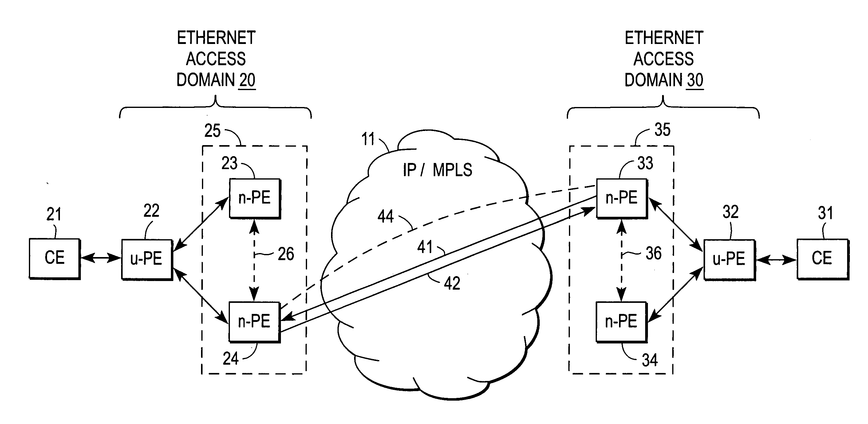
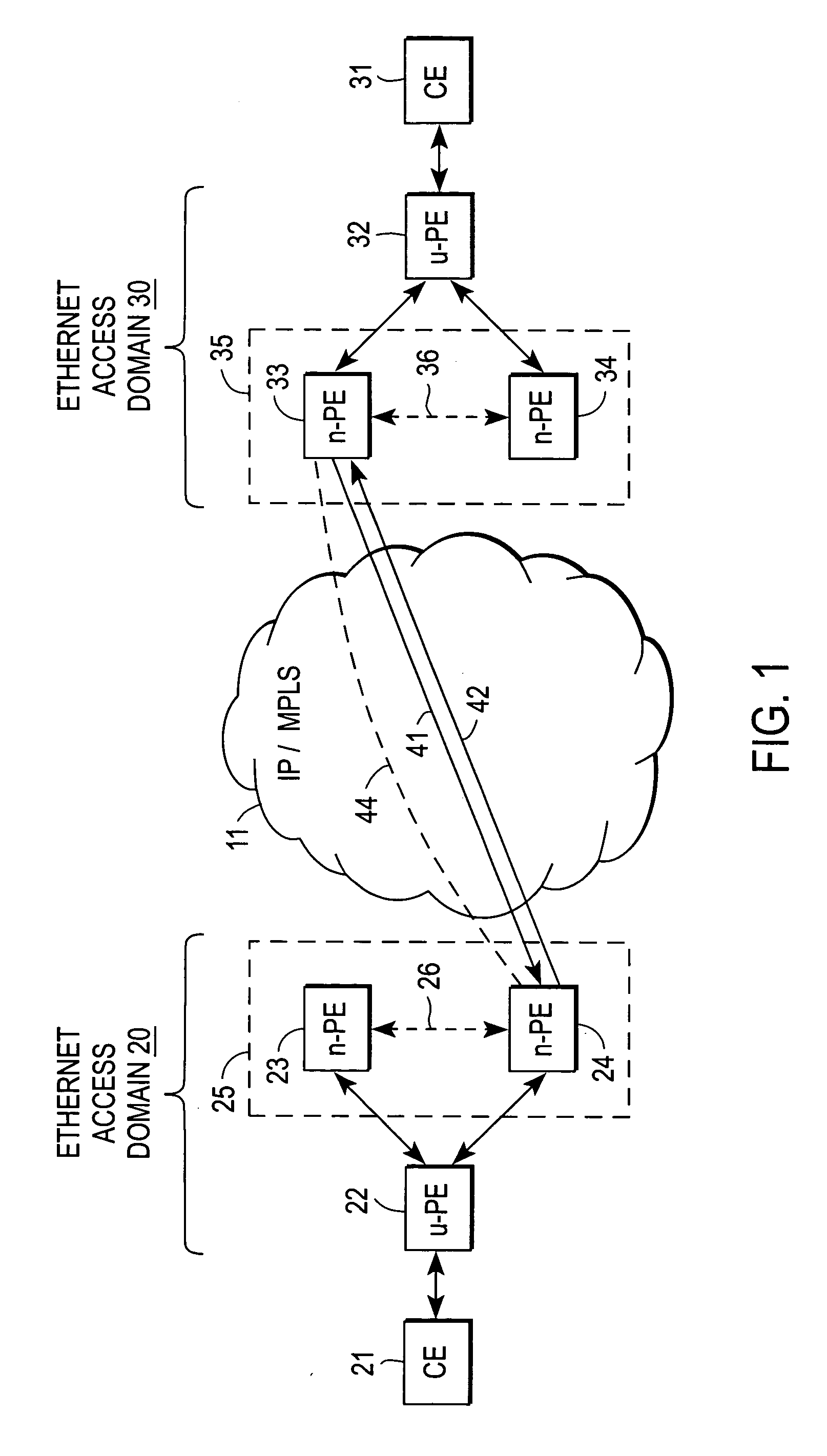
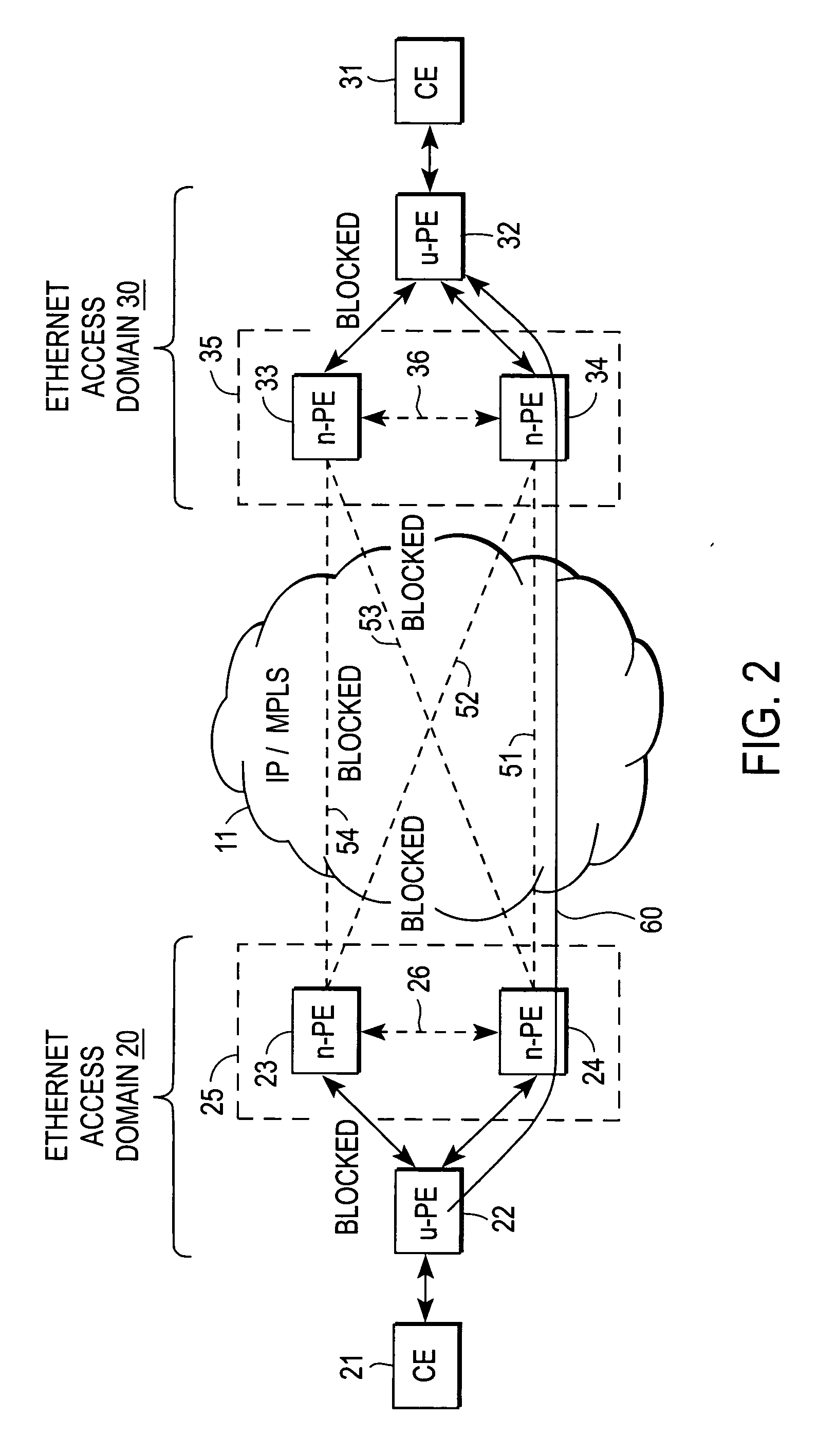
[0020] A network architecture that provides redundant pseudowires between Ethernet access domains without replicated broadcast and multicast packets, “loopbacks”, or a single point of failure is described. In the following description specific details are set forth, such as device types, protocols, configurations, etc., in order to provide a thorough understanding of the present invention. However, persons having ordinary skill in the networking arts will appreciate that these specific details may not be needed to practice the present invention. Practitioners in the network arts will further appreciate that the architecture of the present invention is useful for Ethernet Wire Service (EWS) applications, which emulate point-to-point Ethernet segments, as well as Ethernet Relay Service (ERS) applications, which use VLAN tags to multiplex several non-same-destination pseudowires to a single port.

[0021] A computer network is a geographically distributed collection of interconnected sub...


PUM


Abstract

A computer network includes first and second Ethernet access domain networks, each of Ethernet access domain networks including a user-facing provider edge (u-PE) device, and a stack group of network-facing provider edge (n-PE) devices coupled with the u-PE device, the n-PE devices running a bidding protocol to select one of the n-PE devices as a primary n-PE device for a single pseudowire connection path between the first and second Ethernet access domain networks. It is emphasized that this abstract is provided to comply with the rules requiring an abstract that will allow a searcher or other reader to quickly ascertain the subject matter of the technical disclosure. It is submitted with the understanding that it will not be used to interpret or limit the scope or meaning of the claims. 37 CFR 1.72(b).

Description

RELATED APPLICATIONS [0001] The present application is related to co-pending application Ser. No. 10 / 925,743 filed Aug. 25, 2004, and Ser. No. 10 / 857,716 filed May 28, 2004, both of which are assigned to the assignee of the present application.FIELD OF THE INVENTION [0002] The present invention relates generally to digital computer network technology; more particularly, to methods and apparatus for providing redundancy mechanisms for network connections. BACKGROUND OF THE INVENTION [0003] The performance of many applications benefit from being implemented over service provider networks that support multipoint network services. A multipoint network service is one that allows each customer edge (CE) end point or node to communicate directly and independently with all other CE nodes. Ethernet switched campus networks are an example of a multipoint service architecture. The multipoint network service contrasts with more traditional point-to-point services, such as hub-and-spoke network ...

Claims


Application Information

Patent Timeline
Patent Type & Authority Applications(United States)
IPC IPC(8): H04L12/56H04L12/66
CPCH04L12/462
Inventor VOIT, ERICTOWNSLEY, WILLIAM MARK
Owner CISCO TECH INC
Why Eureka
Try Eureka