Data transmission method and data transmission apparatus

a data transmission and data technology, applied in the direction of orthogonal multiplex, multiplex communication, multi-frequency code system, etc., can solve the problem of signal to noise ratio degraded on the reception end, and achieve the effect of stable data transmission

Inactive Publication Date: 2007-01-11
FUJITSU LTD
View PDF6 Cites 19 Cited by
  • Summary
  • Abstract
  • Description
  • Claims
  • Application Information

AI Technical Summary

Benefits of technology

[0038] The minimum 16 channels may be needed for enabling link equation on the reception end, and, in order to perform effective interleaving while 16 channels are ensured, the minimum 256 channels may be needed in case of performing the ADM transform. However, as the number of signal points thus increases, the above-mentioned PAR increases, and, thereby, the signal to noise ratio on the reception end is degraded. In order to solve this problem, the present invention reduces the number of signal points so as to effectively reduce the PAR.
[0039] The present invention is directed to achievement of predetermined two-dimensional interleaving with a reduced number of channels, and achievement of zero point insertion equivalently. Moreover, another object of the present invention is to make uniform originally non-uniform noise having different characteristics between the time axis and frequency axis, by two fast Fourier transform units (FFT) on the reception end and two-dimension inverse interleaving unit provided between these fast Fourier transform units there. Further, another object of the present invention is to prevent the number of channels of the fast Fourier transform unit from increasing.
[0046] Thereby, according to the present invention, two-dimensional interleaving is performed along the time axis and along the frequency axis, and the data is transmitted by the multi-carrier transmission form. In the reception part, two-dimensional inverse interleaving is performed by the time-and-frequency inverse interleaving unit provided between first and second fast Fourier transform units (FFT) 25 and 30, and, thus reception processing is carried out there. Thereby, equalization of noise components within the relevant band is achieved. Accordingly, even when a data transmission path having large fluctuation / unevenness in noise such as a low-voltage power line as mentioned above, stable data transmission can be performed. Moreover, the number of channels which is short for the number of channels required for the fast inverse Fourier transform can be easily obtained by channel copy, i.e., copying of channels of data.

Problems solved by technology

However, as the number of signal points thus increases, the above-mentioned PAR increases, and, thereby, the signal to noise ratio on the reception end is degraded.

Method used


Image

  • Data transmission method and data transmission apparatus
  • Data transmission method and data transmission apparatus
  • Data transmission method and data transmission apparatus

Examples


first embodiment

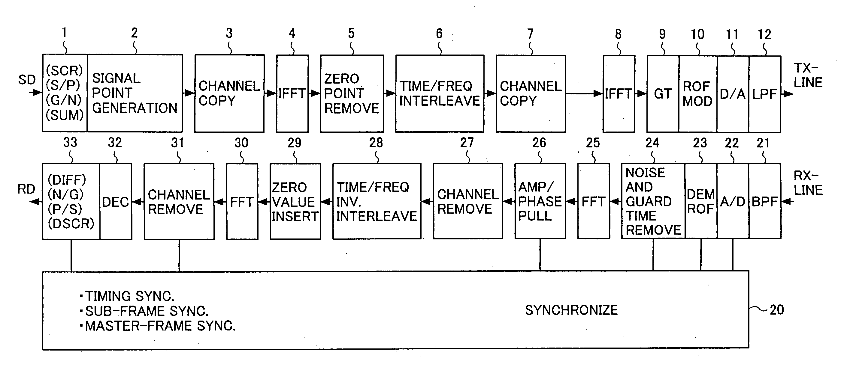
[0069]FIG. 12 illustrates a data transmission apparatus in the present invention. In this data transmission apparatus, a transmission signal SD is input to a code conversion unit 1, and, further, the apparatus includes a signal point generating unit 2, a first channel copy unit 3, a first fast inverse Fourier transform unit (IFFT) 4, a zero point removal unit 5, a time-and-frequency interleaving unit 6, a second channel copy unit 7, a second fast inverse Fourier transform unit (IFFT) 8, a guard time insertion unit (GT) 9, a roll-off filter and modulation unit (ROFMOD) 10, a D-A conversion unit (D / A) 11, and a low-path filter (LPF) 12. The thus-processed transmission signal is sent out through a transmission circuit TX-line. The above-described configuration is of a transmission part of the data transmission apparatus.

[0070] On the other hand, through a reception circuit RX-line, a transmission signal is received by the data transmission apparatus. Then, this signal is input to a ban...

second embodiment

[0092] The functions and operations of the first and second fast inverse Fourier transform units 4 and 8, and the time-and-frequency interleaving unit 6 are the same as those in the case shown in FIG. 12. With regard to the reception part, not 64 channels but 16 channels or 32 channels are input to and output from the second fast Fourier transform unit 34 in the Thereby, the zero value insertion unit 29 and channel removal unit 31 shown in FIG. 12 are omitted. The other functions and operations are the same as those of the case shown in FIG. 12, and duplicate description is omitted.

[0093]FIG. 21 illustrates transition of the number of channels in the second embodiment. Adding a single zero value each time corresponds to copying once (take a single copy) each time in FIG. 13, and, similarly, adding add three zero values corresponds to copying thrice (take three copies) shown in FIG. 13. That is, in order to provide 64 channels to the first fast inverse Fourier transform unit 4, zero...


PUM


Abstract

A data transmission method comprises the steps of: a) performing two-dimensional interleaving along a time axis and along a frequency axis; b) transmitting the thus-obtained data by a multi-carrier transmission form; and c) producing, by channel copy operation, data which is short for the number of channels required for fast inverse Fourier transform performed antecedent and subsequent to said step a).

Description

CROSS REFERENCE TO RELATED APPLICATION [0001] This application is a divisional of U.S. application Ser. No. 10 / 047,131 filed Jan. 15, 2002, now pending, and claims priority from Japanese Application 2001-186274 filed Jun. 20, 2001, the contents of which are herein incorporated by reference.BACKGROUND OF THE INVENTION [0002] 1. Field of the Invention [0003] The present invention relates to a data transmission method and a data transmission apparatus performing two-dimensional interleaving operation along a frequency axis and along a time axis on transmission data, and the data is transmitted according to a multi-carrier transmission form. The present invention may be applied not only to a power-line transmission field, but also, for a cable transmission field, ADSL, VDSL, CATV and so forth, and, for a wireless transmission field, wireless LAN of 2.4 GHz, digital broadcasting, and so forth, and, also, for an optical data transmission field, WDM, and so forth. [0004] 2. Description of ...

Claims


Application Information

Patent Timeline
Patent Type & Authority Applications(United States)
IPC IPC(8): H04L27/00H04K1/10H04J11/00H04L1/00H04L27/26
CPCH04L1/0071H04L27/2602H04L27/2614H04L27/265H04L27/2628H04L27/26538H04L27/26524H04L27/2634
Inventor KAKU, TAKASHIHIRAO, KYOKO
Owner FUJITSU LTD
Why Eureka
Try Eureka