Injection mold for forming free-form surface optical element, free-form surface optical element and free-form surface mirror formed by employing the injection mold

a technology of injection molds and optical elements, which is applied in the field of injection molds, can solve the problems of unstable relation between the mirror surface and the mounting reference surface, difficult adjustment, and difficult adjustment, and achieve the effects of high accuracy, low cost, and easy adjustment of mounting

Inactive Publication Date: 2007-01-11
KONICA MINOLTA OPTO
View PDF15 Cites 9 Cited by
  • Summary
  • Abstract
  • Description
  • Claims
  • Application Information

AI Technical Summary

Benefits of technology

[0055] Also, as the gate is provided on the ear portion positioned at the lower end of the free-form surface mirror, influences such as minute swell of the flowing resin on the mirror surface is less, enabling to form the mirror with high accuracy.
[0056] According to the present invention, as the free-form surface and the mounting reference surfaces are positioned in the mold on the same side with respect to the parting line, the position accuracy of the free-form surface and the mounting reference surfaces can be set in the same mold, making the relation between the free-form surface and the mounting reference surfaces stable in spite of displacement, inclination and so on of the mold. Therefore, it is easy to adjust when mounting and it is possible to produce with high accuracy at low cost a free-form surface optical element.
[0057] In addition, according to the present invention, as the contour of the mirror is formed along the periphery of the effective area, the outline is not enlarged more than needs and has no dead area. Also, as the corner portions of the outline are formed to have a radius of curvature larger than the thickness of the corner portions, the molding resin has a good melt flow rate and an excellent formability.

Problems solved by technology

The free-form surface mirror can not have an optical axis, causing a difficulty of adjustment when mounting it.
As the mounting reference surface is formed by different mold from that of the mirror surface, the relation between the mirror surface and the mounting reference surface is unstable due to displacement, inclination and so on of the mold.
This makes it very difficult to adjustment when mounting the mirror and increases fabrication cost and also greatly affects the quality of image.
However, the free-form surface mirror has a large mirror volume more than needs, causing a long molding time and a disadvantage on cost.
In addition, the large contour of the mirror often causes an interference with other parts and makes it difficult to miniaturizing the projection unit.

Method used


Image

  • Injection mold for forming free-form surface optical element, free-form surface optical element and free-form surface mirror formed by employing the injection mold
  • Injection mold for forming free-form surface optical element, free-form surface optical element and free-form surface mirror formed by employing the injection mold
  • Injection mold for forming free-form surface optical element, free-form surface optical element and free-form surface mirror formed by employing the injection mold

Examples


Embodiment Construction

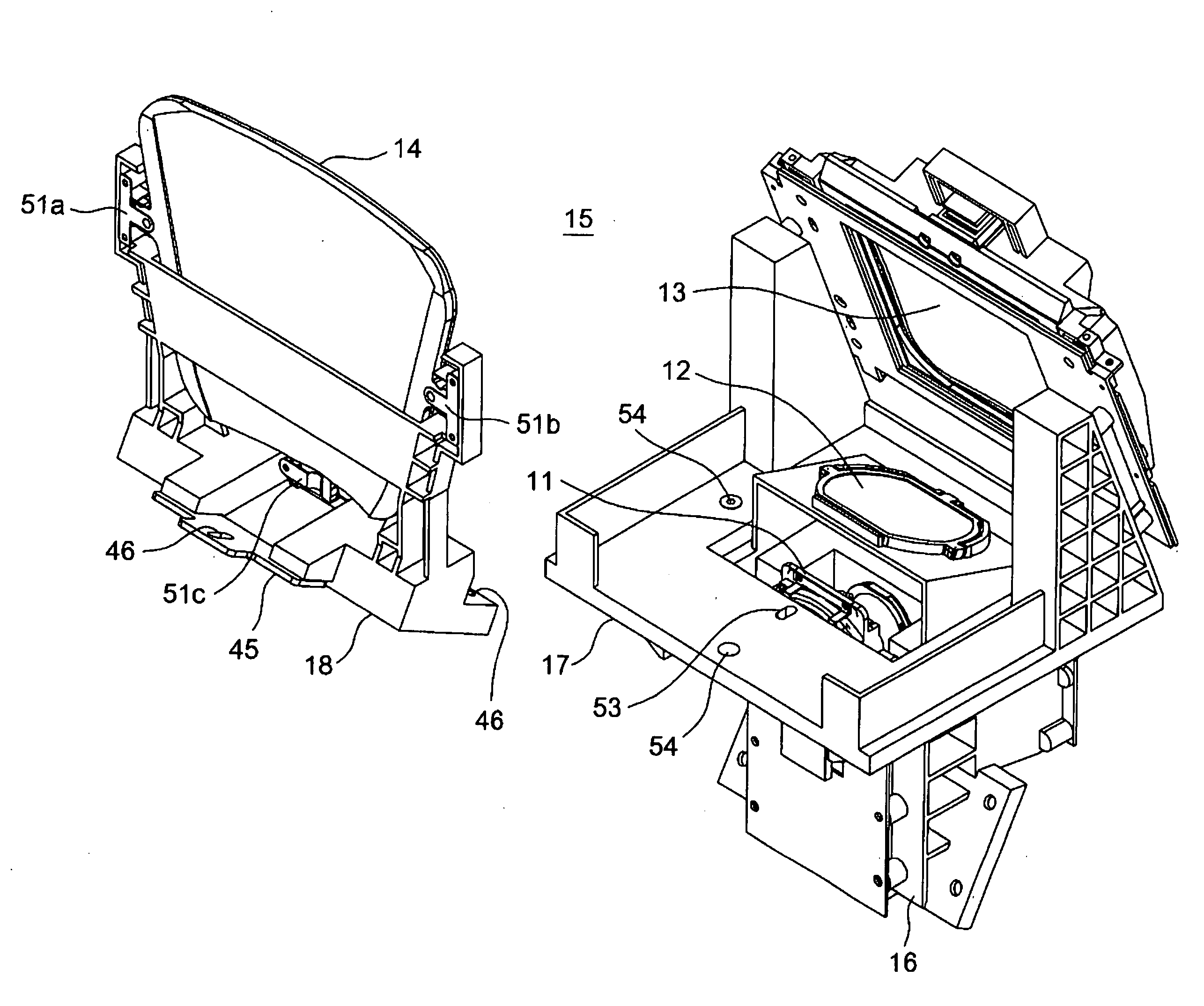
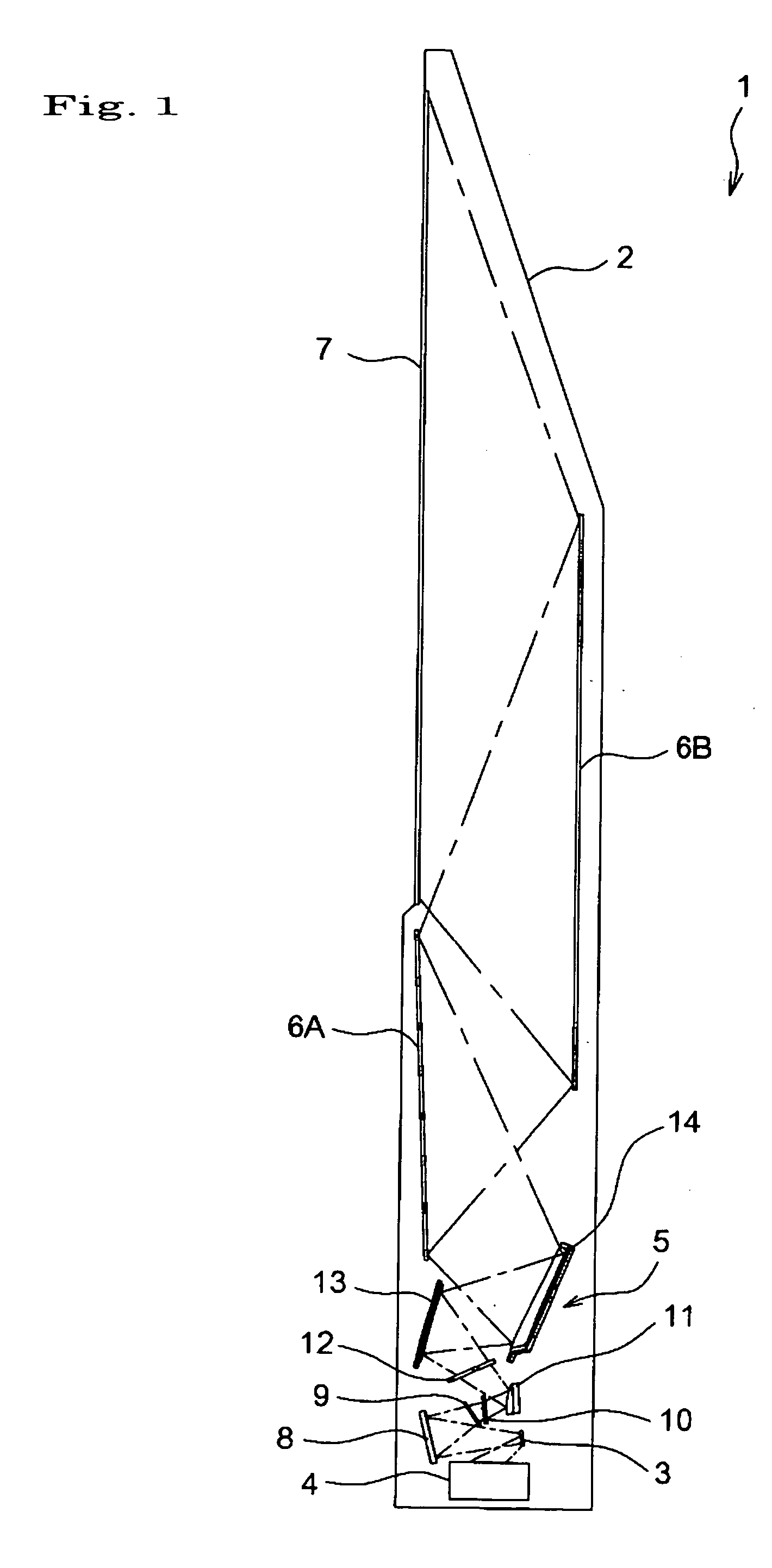
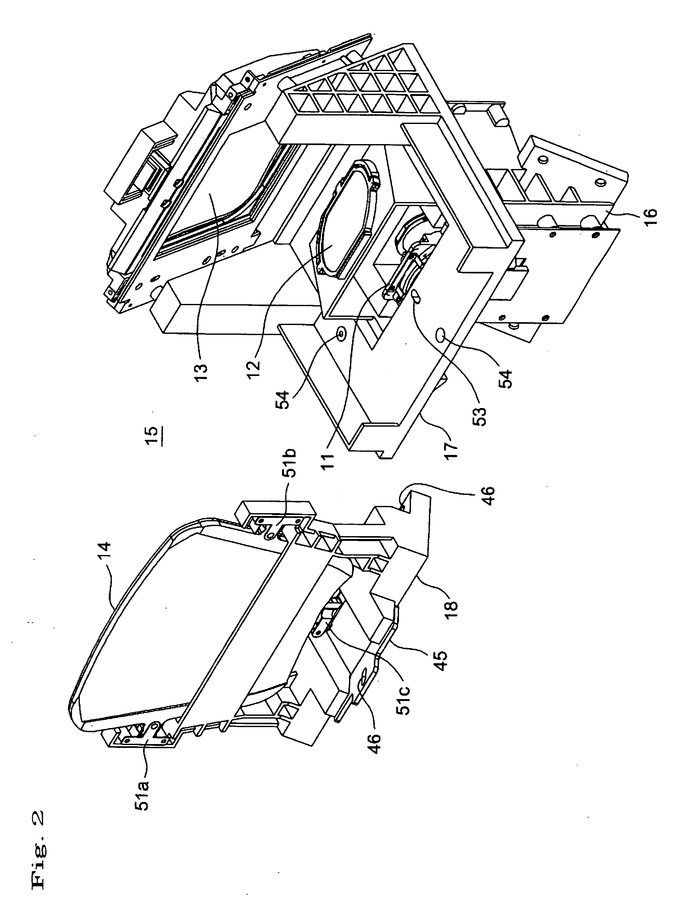
[0077]FIG. 1 shows a rear-projection television 1 (rear-pro TV) as an embodiment of a projection type of image displaying apparatus having free-form surface mirror according to the present invention. In a casing 2 of the rear-pro TV 1 are housed a digital micro mirror device (DMD) 3 as one example of the reflection type of image forming element, an illumination optical system 4 for irradiating the DMD 3 with an illumination light and a projection optical system 5 for enlarging and projecting a projection light, i.e., an image light reflected on the DMD 3. On the upper portion of the front surface of the casing 2 is provided a screen 7 on which the image enlarged by the projection optical system 5 is projected through two plane mirrors 6A, 6B.

[0078] In the projection optical system 5, in the order from the side of DMD 3, there are disposed a concave mirror 8, a variable aperture mechanism 9, a first aberration correction plate 10, a convex mirror 11, a second aberration correction p...


PUM

PropertyMeasurementUnit
areaaaaaaaaaaa
thicknessaaaaaaaaaa
thicknessaaaaaaaaaa

Abstract

The present invention provides an injection mold for forming free-form surface optical element that is possible to produce with high accuracy at low cost a free-form surface optical element that has a stable relation between the free-form surface and the mounting reference surface and is easy to adjust when mounting. The mold comprises a fixed mold and a movable mold for forming a free-form surface (effective area 21) and a rear surface opposite to the free-form surface. The fixed mold and the movable mold are divided by a parting line PL along the peripheral end surface of the free-form surface optical element 14. A mold surface for molding the free-form surface (effective area 21) and a mold surface for molding axial-direction mounting reference surfaces 28a-28c for mounting the free-form surface optical element in a direction substantially perpendicular to the free-form surface are positioned in the mold on the same side with respect to the parting line PL.

Description

[0001] This application is based on Japanese Patent Application Nos. 2005-198727, 2005-202648 the contents in which are incorporated herein by reference. BACKGROUND OF THE INVENTION [0002] The present invention relates to an injection mold for forming an free-form surface optical element used for a projection type of image displaying apparatus, i.e., rear-projection television, front-projection television and video projector provided with a reflection type of image forming element such as DMD (digital micro mirror device) or a transparent type of image forming element such as transparent liquid crystal element. Also, the present invention relates to a free-form surface optical element and a free-form surface mirror formed by employing the injection mold. [0003] Recently, there has been a great demand for a projection type of image displaying apparatus having large surface and thin profile. The free-form surface mirror is an indispensable part for attaining large surface and thin pro...

Claims


Application Information

Patent Timeline
Patent Type & Authority Applications(United States)
IPC IPC(8): B29D11/00
CPCB29C33/005B29C45/0025B29C2045/0034H04N9/3141B29L2011/0058B29L2031/3475G03B21/10B29C2045/0093B29C45/37B29L2011/00G02B5/10
Inventor OKUMURA, YOSHIHIROWATARU, KOHEIIMAOKA, MASAYUKIISHIHARA, JUNMATSUURA, ATSUSHI
Owner KONICA MINOLTA OPTO
Why Eureka
Try Eureka