Eureka AIR delivers breakthrough ideas for toughest innovation challenges, trusted by R&D personnel around the world.

Biological imaging systems

Inactive Publication Date: 2007-01-11
PEREZ TIMOTHY
View PDF0 Cites 14 Cited by
  • Summary
  • Abstract
  • Description
  • Claims
  • Application Information

AI Technical Summary

Benefits of technology

[0010] The housing is adapted to be at least partially inserted within the body of the patient, and can function as its own insertion device thus eliminating the need for a separate trocar. The image capture element is mounted with the housing such that when in use, the image capture element is within the body of the patient, and further such that the image capture element is adapted to generate a sign

Problems solved by technology

This technique was limited initially since the surgeon had to put his eye to lens and was mainly for diagnostic purposes and very simple procedures.
Despite almost a century of use, there remain numerous significant problems with the instrumentation available for laparoscopic surgery and observation.
This is not always possible and the deviation from this alignment distorts the surgeon's view.
Conventional technology provides digital images, but does not provide any compensation for the various forms of visual distortion.
However, as a cylindrical laparoscope has no fixed rotational orientation, there can be a tendency for the instrument to roll or rotate about its longitudinal axis defined by the arrow B, thus potentially skewing the orientation of the image displayed on the monitor 7.
Thus any movement of the laparoscope is potentially problematic, as there are a number of degrees of freedom in the conventional system, and it is a taxing effort to maintain the proper horizontal and rotational orientation of the laparoscope and the resulting image used by the surgeon.
The mental and physical fatigue associated with operating the laparoscope can degrade accuracy of the camera holder thus slowing the operation or procedure.
This leads to several significant weaknesses noted above, including: (1) a conventional laparoscope is a round tube inserted through a round opening, creating a tendency to deviate from the horizontal thus skewing the image; (2) the imaging surface of the lens is small which limits the amount of pixel data gathered; (3) the small lens area is prone to soiling from water vapor, blood, etc, and needs to be cleaned frequently.
Prior advances in laparoscope technology have been limited to imaging technology.
However, laparoscopic surgery is not “watching television”.
Instead of enhancing the surgeon's visual information, conventional laparoscopes inadvertently often contribute to its limitation.

Method used


Image

  • Biological imaging systems
  • Biological imaging systems
  • Biological imaging systems

Examples


Embodiment Construction

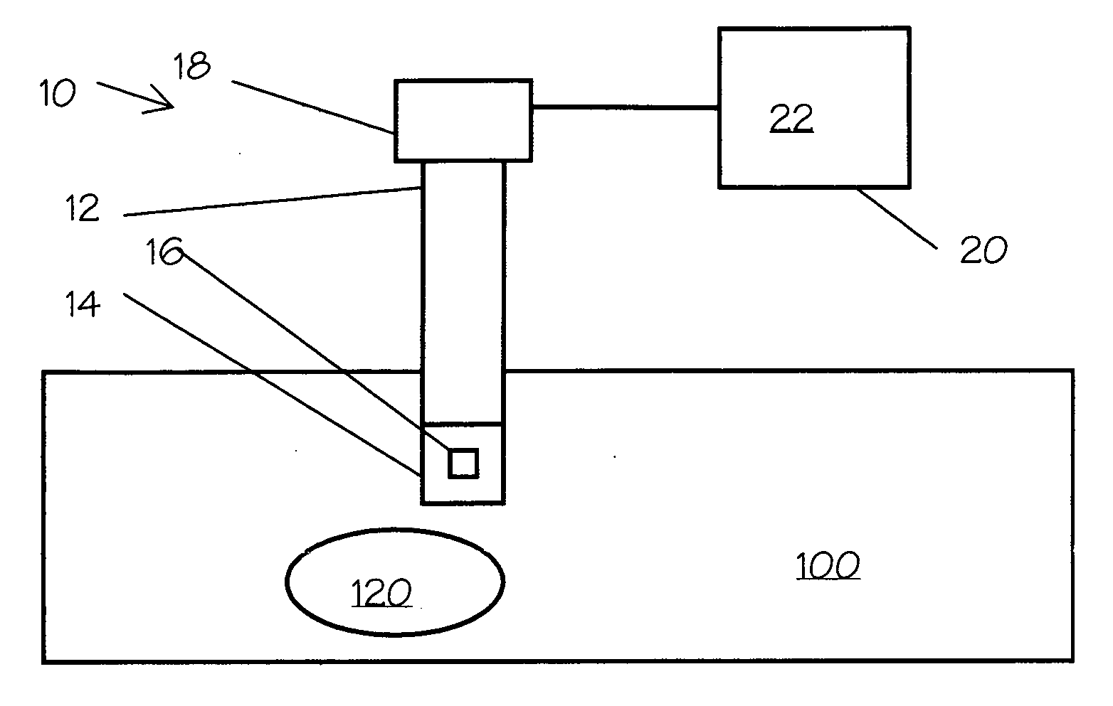
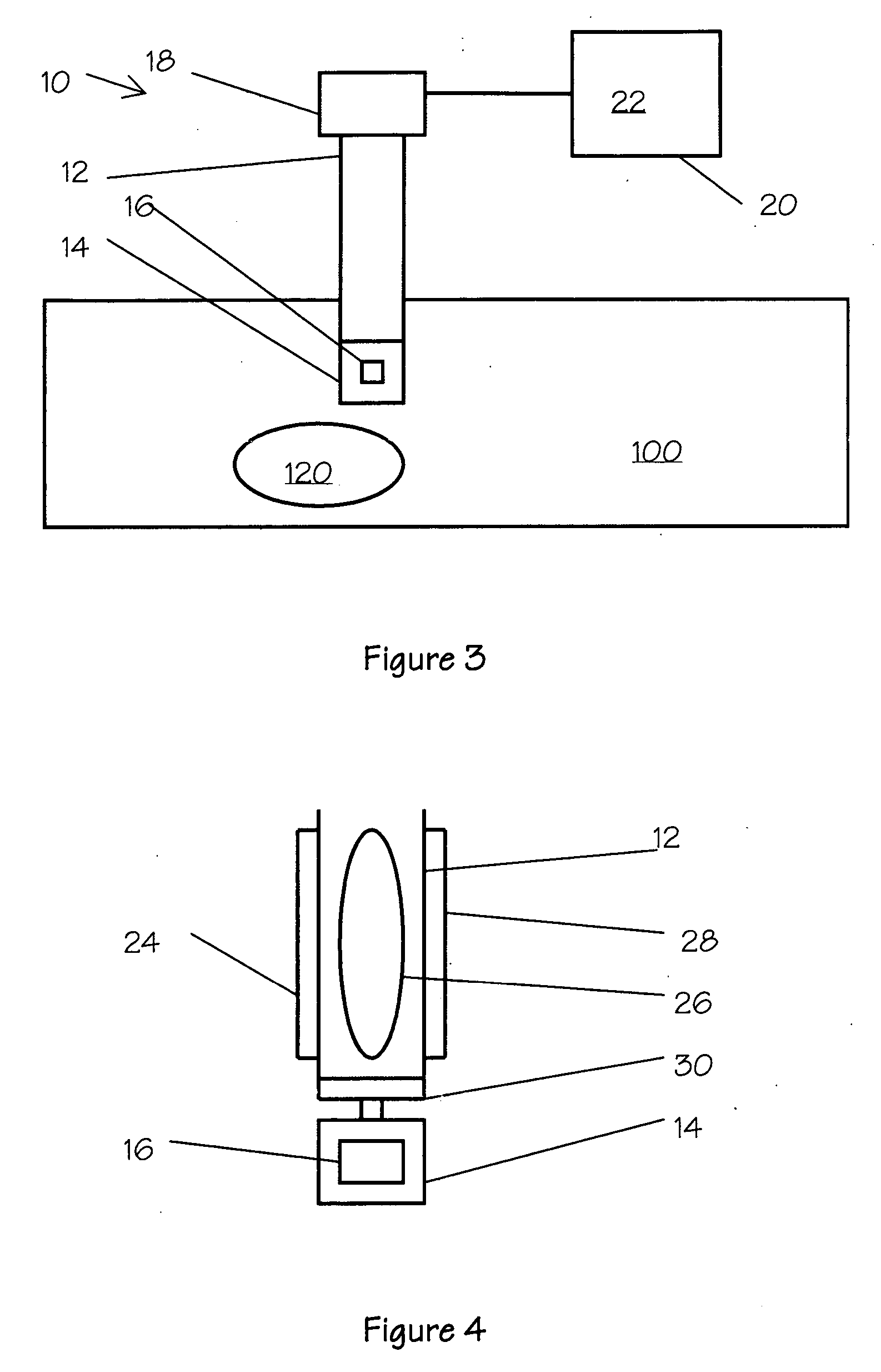
[0017] As shown in FIGS. 3 through 5, the present invention includes a laparoscopic imaging apparatus 10 adapted to provide a number of improvements over the prior art. An example imaging apparatus 10 includes a housing 12, mountable in a known relationship to a patient, an image capture element 14 mounted with the housing 12, and an image control system 18 connected to the image capture element 14.

[0018] The example housing 12 is adapted to be at least partially inserted within the body of the patient, and can function as its own insertion device thus eliminating the need for a separate trocar. In other variations from the example embodiment, the housing 12 is adapted to be substantially fixed relative to the skin of the patient, thus minimizing any movement of the imaging apparatus 10 and reducing the risk of any damage to the tissues surrounding the incision through which the imaging apparatus is 12 inserted into the patient's body. As used herein, the term skin refers to the ep...


PUM


Abstract

The present invention includes a laparoscopic imaging apparatus including a housing mountable in a known relationship to a patient, an image capture element mounted with the housing, and an image control system connected to the image capture element. The image capture element is mounted with the housing such that when in use, the image capture element is within the body of the patient, and further such that the image capture element is adapted to generate a signal representative of an image of portions of the volume within the body of the patient. The image control system is adapted to be responsive to the signals generated by the image capture element as well as control inputs provided by a user. The image control system is further adapted to select a portion of an image represented by the signal, wherein the portion of the image is less than the whole image.

Description

CROSS-REFERENCE TO RELATED APPLICATIONS [0001] The present application claims priority under 35 U.S.C. 119 to provisional application Ser. No. 60 / 698,207, filed Jul. 9, 2005.FIELD OF THE INVENTION [0002] This invention relates generally to the field of surgery, medical devices and optical instruments, and in particular to systems and devices for minimally invasive surgery and observation within the abdominal cavity. BACKGROUND OF THE INVENTION [0003] Laparoscopy (visualization of the abdominal cavity) has been performed since the beginning of the 20th century. FIG. 1 shows the relative configuration of a present laparoscopic system 1 and an abdominal cavity 100, including an object of interest 120 therein. A rigid lens 4 is introduced through the body wall with the support of a trocar 2, which allows a surgeon to look inside the abdominal cavity 100. This technique was limited initially since the surgeon had to put his eye to lens and was mainly for diagnostic purposes and very simp...

Claims


Application Information

Patent Timeline
IPC IPC(8): A61B1/04
CPCA61B1/3132A61B1/00039
Inventor PEREZ, TIMOTHY
Owner PEREZ TIMOTHY
Why Eureka
Eureka Blog
Learn More