Method and system for creating snapshots by condition
a snapshot and condition technology, applied in the field of storage device systems, can solve the problems of increasing the cost of the storage device system, and achieve the effect of efficient use of the storage area
- Summary
- Abstract
- Description
- Claims
- Application Information
AI Technical Summary
Benefits of technology
Problems solved by technology
Method used
Image
Examples
case 4
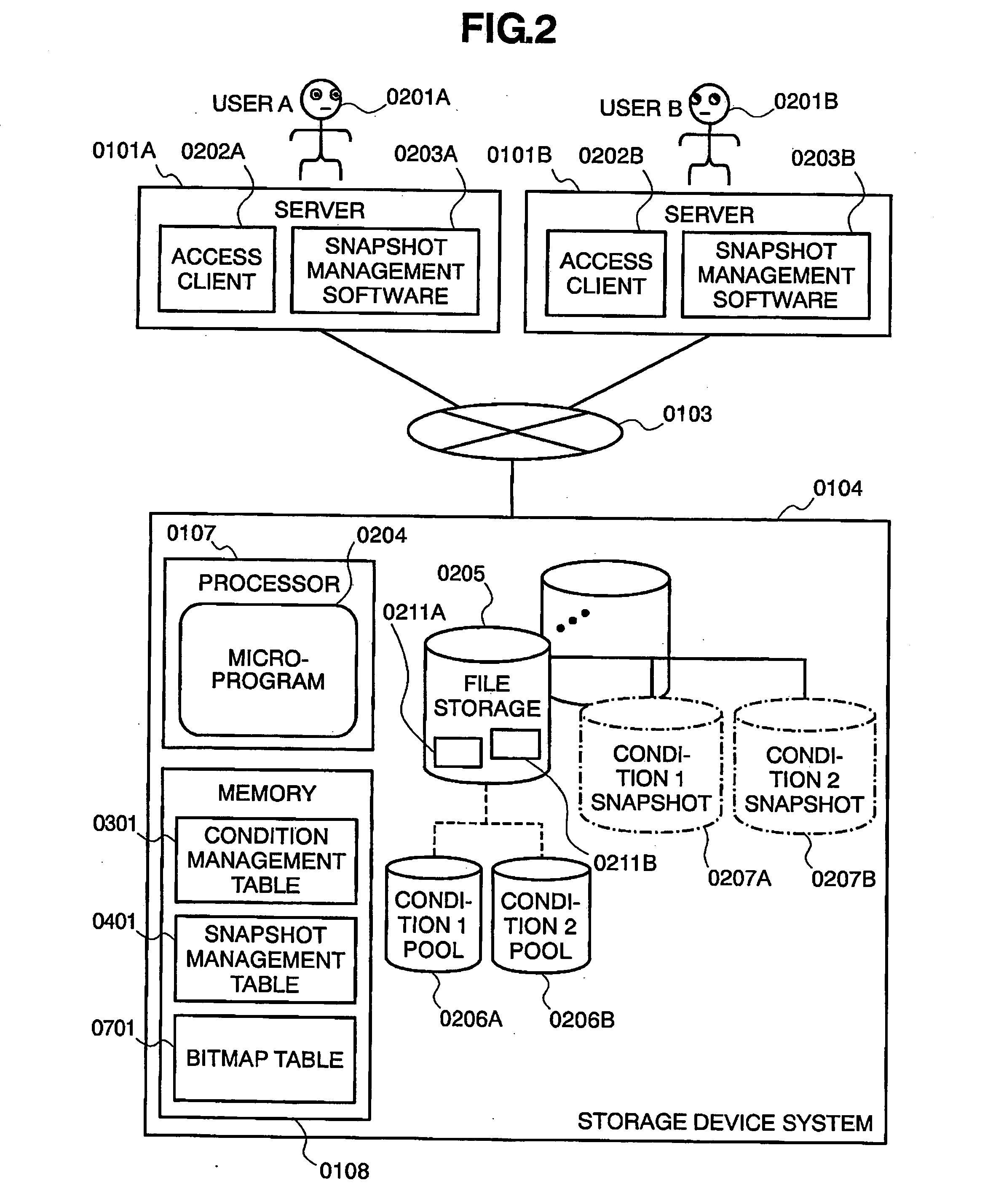
[0149] Case 4 is equivalent to the processing in step 1206, and shows an example of a file read request from the access client 0202 for the snapshot S7. The snapshot inode information 0601 corresponding to the snapshot S7 is not linked to the inode information inode information 0501. The micro-program 0204 then checks for snapshots having a snapshot number greater than the snapshot S7 under the same conditions as the snapshot S7. The snapshot S8 satisfies these conditions in this example. The micro-program 0204 then reads data from the snapshot S8.
case 5
[0150] Case 5 is equivalent to the processing in step 1207, and shows an example of processing a file read request from the access client 0202 for the snapshot S12 at time T13. In this case, the snapshot inode information 0601 of the snapshot S12 is not linked to the file inode information 0501, and since a snapshot for which the snapshot number is greater than the snapshot S12, and conditions are the same, does not exist, the micro-program 0204 references the inode information 0501 and reads the data.
[0151]FIG. 18 shows an example of snapshot delete processing executed by the micro-program 0204.
[0152] As with the snapshot creation request, the user 0201 and manager issue a snapshot delete request for the storage device system 0104, and this request is received by the micro-program 0204 (step 1501). The snapshot delete request includes a snapshot number.
[0153] The micro-program 0204 checks each inode information 0501 to determine whether or not snapshot inode information 0601 havi...
case 7
[0159] Case 7 is equivalent to the processing from step 1505 through 1507, and is the case in which the snapshot delete request is for the snapshot S12. In this case, since the immediately previous snapshot S8 has snapshot inode information, the snapshot S12 entry is deleted.
[0160] In Case 8 the snapshot S7 is deleted, and since the snapshot S7 has no snapshot inode information 0601, the micro-program 0204 deletes the S7 entry from the snapshot management table.
[0161] Processing in step 1502 and later can be run as a background job to ensure that the performance of file access processing is not affected.
[0162]FIG. 19 shows an example of file delete processing executed by the micro-program 0204.
[0163] The micro-program 0204 receiving the file delete request from the server 0101a or the server 0101b deletes the file entry from the file link source directory file (step 1301). At this time, the micro-program 0204 executes the file write processing in FIG. 13 in order to update the di...
PUM
 Abstract
Description
Claims
Application Information
 - R&D
- Intellectual Property
- Life Sciences
- Materials
- Tech Scout
- Unparalleled Data Quality
- Higher Quality Content
- 60% Fewer Hallucinations
Browse by: Latest US Patents, China's latest patents, Technical Efficacy Thesaurus, Application Domain, Technology Topic, Popular Technical Reports.
© 2025 PatSnap. All rights reserved.Legal|Privacy policy|Modern Slavery Act Transparency Statement|Sitemap|About US| Contact US: help@patsnap.com


