Thermal method for ice removal under ambient air cryogenic vaporizers

a cryogenic vaporizer and ambient air technology, applied in the direction of defrosting, domestic cooling apparatus, container discharge methods, etc., can solve the problems of inability to remove frozen water debris at the base of heat transfer surfaces, accumulation of ice over time, and inability to mechanically remove piles

Inactive Publication Date: 2007-01-18
CRYOQUIP
View PDF9 Cites 8 Cited by
  • Summary
  • Abstract
  • Description
  • Claims
  • Application Information

AI Technical Summary

Benefits of technology

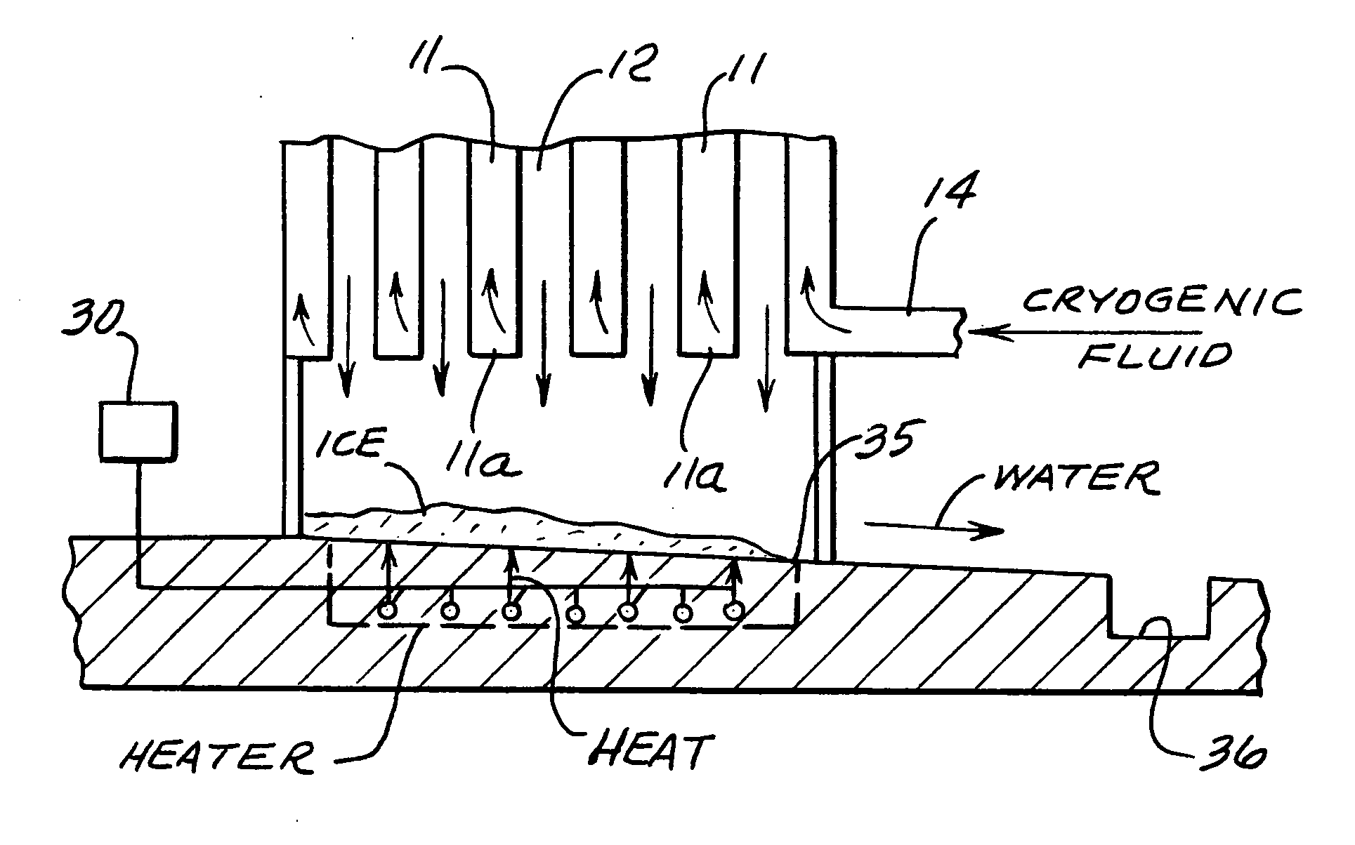
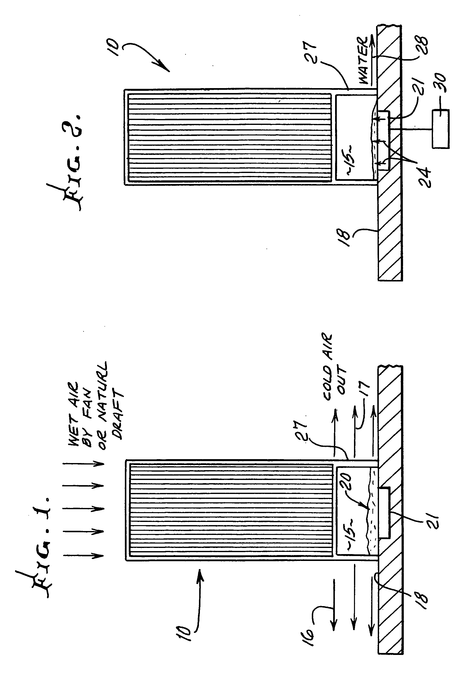
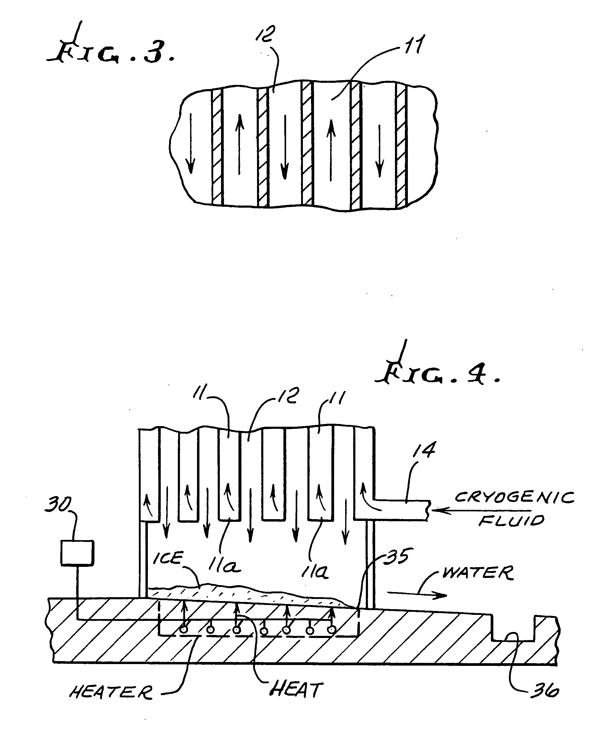
[0002] By supplying supplemental heat at the bases of the units, the frost / ice can be melted during a thaw cycle. Then the melted water can be moved by either gravity or a pump to disposal point. The amount of added heat is small relative to the total duty of the unit.

Problems solved by technology

As arrays of vaporizers become larger to service large consumers such as steel mills, or LNG receiving and send-out terminals, frozen water debris at the bases of the heat transfer surfaces is not removed and accumulates over time.
The large number of vaporizers units and their relatively close spacing preclude sufficient ambient air circulation to melt the pile.
Similarly, it is not practical to remove the pile mechanically.

Method used


Image

  • Thermal method for ice removal under ambient air cryogenic vaporizers
  • Thermal method for ice removal under ambient air cryogenic vaporizers
  • Thermal method for ice removal under ambient air cryogenic vaporizers

Examples


Embodiment Construction

[0022] In FIG. 1, each vaporizer unit 10 has passages to pass cryogenic fluid upwardly in passages in heat transfer relation with ambient air flowing downwardly in adjacent passages. FIG. 3 shows such passages 11 and 12 in greater detail. FIG. 4 shows that the cryogenic fluid may be supplied to the bottom inlets 11a to passages 11 via a manifold 14. The vaporized (gasified) cryogenic fluid may be removed as by manifolding at the upper ends of the passages 11. Ambient air normally containing some moisture flows downwardly through the passages 12, which are open at their upper and lower ends, and such cooled air is received in a space 15 below the vaporizer unit. Cold air in space 15 flows laterally, as indicated by arrows 16 and 17 indicating opposite directions of flow, to the exterior, above base 18. As referred to above, ice and frost forms on upright surfaces in the vaporizer, and tends to fall in passages 12 to space 15, where it collects in a pile of ice and slush indicated at ...


PUM


Abstract

This invention relates prolonging operation duration of ambient air heated vaporizers of cryogenic fluids; and more particularly concerns a method for enhancing ice removal under such vaporizers. Ambient air vaporizers have been used in the past to convert cryogenic fluids into warm gas. Because of the very cold surfaces inherent in the construction of these vaporizers, they collect frost or ice, and are generally limited in the time they can be effective due to the reduction in heat transfer caused by the frozen atmospheric water collecting on vaporizer surfaces. Operators frequently seek to mitigate this effect by having multiple vaporizers, alternately switching units on and off, allowing them to defrost. A characteristic of these defrosting vaporizers, is the falling of the frost and ice off the heat transfer surfaces, collect at the base of the unit (the “Pile). This Pile of frozen water or slush generally can be melted by exposure to warm ambient air during the defrost cycle. The Pile also can be removed manually.

Description

[0001] As arrays of vaporizers become larger to service large consumers such as steel mills, or LNG receiving and send-out terminals, frozen water debris at the bases of the heat transfer surfaces is not removed and accumulates over time. The large number of vaporizers units and their relatively close spacing preclude sufficient ambient air circulation to melt the pile. Similarly, it is not practical to remove the pile mechanically. SUMMARY OF THE INVENTION [0002] By supplying supplemental heat at the bases of the units, the frost / ice can be melted during a thaw cycle. Then the melted water can be moved by either gravity or a pump to disposal point. The amount of added heat is small relative to the total duty of the unit. [0003] Accordingly, it is a major object of the invention to provide a method of converting cryogenic fluid to gas, which includes the steps a) providing and operating a vaporizer having passages to pass the cool or cold cryogenic fluid in heat transfer relation wi...

Claims


Application Information

Patent Timeline
Patent Type & Authority Applications(United States)
IPC IPC(8): F17C9/02
CPCF17C7/04F17C2270/0136F17C2221/033F17C2223/0161F17C2223/033F17C2225/0123F17C2225/036F17C2227/0313F17C2227/0316F17C2227/0332F17C2227/0334F17C2227/0393F17C2260/032F17C2270/0123F17C2265/05
Inventor BROWN, ROSS M.
Owner CRYOQUIP
Why Eureka
Try Eureka