
Gear-driven balance shaft apparatus with backlash control

a technology of gear-driven balance shaft and backlash control, which is applied in the direction of gearing elements, belts/chains/gearrings, hoisting equipments, etc., can solve the problems of acoustic emission, general unsuitability of toothed belt drives for application requirements, and unsuitable for toothed belt drives

Inactive Publication Date: 2007-01-18
METALDYNE BSM
View PDF25 Cites 24 Cited by
  • Summary
  • Abstract
  • Description
  • Claims
  • Application Information

AI Technical Summary

Benefits of technology

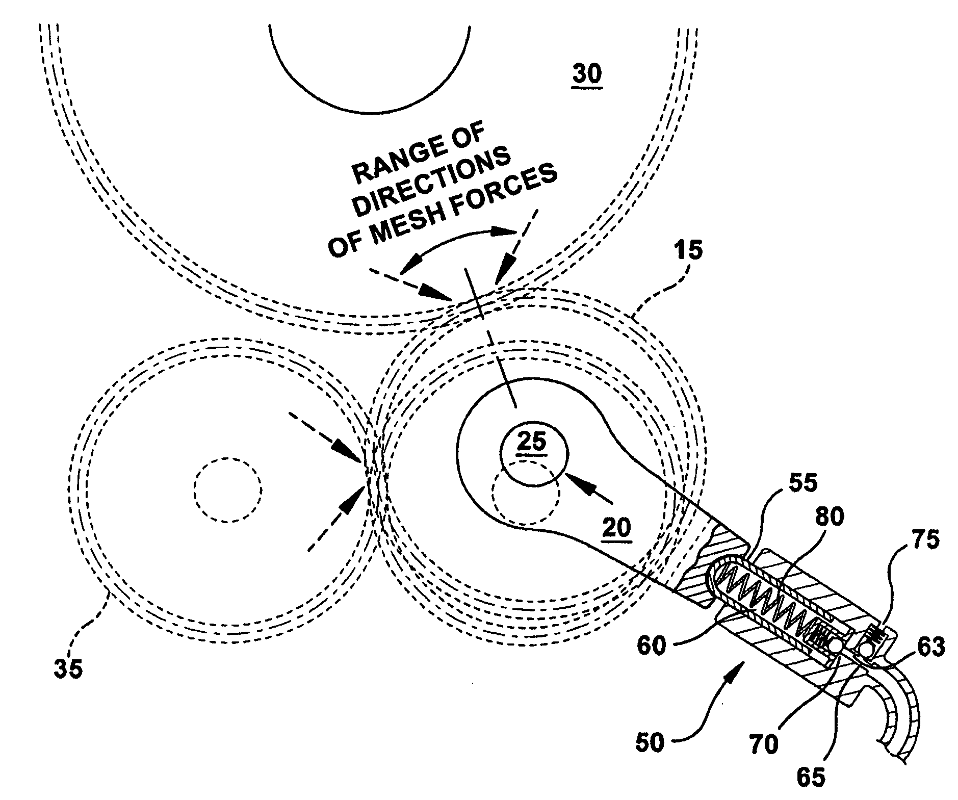
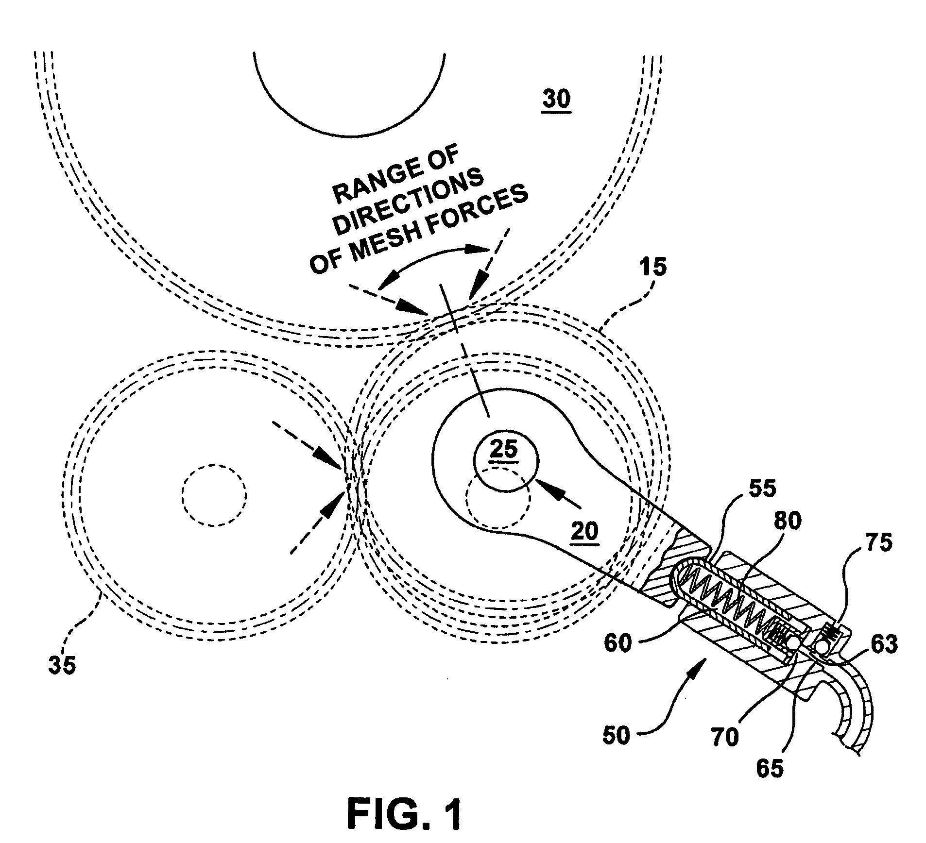
[0009] Therefore, disclosed herein, is the employment of at least one motion control device which utilizes both resilient urging and hysteretic (or viscous) damping, preferably in conjunction with the capture of hydraulic fluid pressure as provided by a host engine's lubricating system, to supply appropriately light resilient biasing of an intermediate gear, towards a crankshaft gear, and preferably also a mating gear, the resilient biasing being fortified against rapid retraction or repulsion of the intermediate gear away from the crankshaft gear by the hysteretic or viscous damping and / or fluid capture.

Problems solved by technology

Chain drives and gearsets are both capable of this functionality, but both introduce acoustic emission issues when trying to do the job alone.
Toothed belt drives are feasible but are generally unsuited to application requirements.
A single-stage 2:1 step-up ratio balance shaft chain drive system, with its 2:1 difference in sprocket sizes, is acoustically challenged by the high chordal action of its relatively “undersized” driven sprocket being combined with the high chain velocities associated with its much larger driver (crankshaft) sprocket.
The chain meshing forces excite engine structures, often resulting in audible emissions.
“Gearset Alone” Challenges—In the case of direct drive gearsets connecting a balance shaft apparatus with a crankshaft-mounted drive gear, the principal engineering challenge is the management of the substantial variations in center distance imposed on the gears by differential thermal expansion effects, tolerance stack-ups, and crankshaft mobility.
Insufficient backlash (forced tight mesh) results in greatly increased meshing noise (or “whine”), and risk of tooth fatigue due to the large cantilever bending loads imposed by the wedging together of the teeth in mesh.
Excessive backlash magnitudes allow sufficient tooth separation magnitude, under the crankshaft's ubiquitous torsional accelerations, as to result in tooth closure impact energy that is large enough to overcome oil film cushioning effects, with the unpleasant result being acoustic emissions (or “rattle”).
With current low viscosity oils and elevated operating temperatures, however, the tooth closure energy associated with excessive backlash can overwhelm the energy absorption capabilities of optimized oil film cushioning effects.
The center distance variations associated with contemporary engine thermal effects alone are so large as to incur backlash variations which compromise the acoustic performance of conventional direct drive gearsets under very ordinary thermal operating ranges.
The drawbacks of scissors gears are known to include meshing noise, durability, and very high manufacturing cost.
Meshing noise arises from the high tooth loadings which accompany the resilient biasing between side-by-side paired (or “split”) gear members, and is exacerbated by the compromises in contact ratio that result from the packaging space sharing that is required of these side-by-side gear members.
Durability challenges are posed by the abnormally high tangential tooth loading required to directly convey the inertia torques of torsional vibrations imposed on the gearsets, in conjunction with the packaging space-dictated narrowness of gear members.
Substantial manufacturing costs arise from the extreme precision required for location and runout control of the biasing gear member with respect to the fixed member, and the high material property demands placed by the high tangential tooth loads.

Method used


Image

  • Gear-driven balance shaft apparatus with backlash control
  • Gear-driven balance shaft apparatus with backlash control
  • Gear-driven balance shaft apparatus with backlash control

Examples


Embodiment Construction

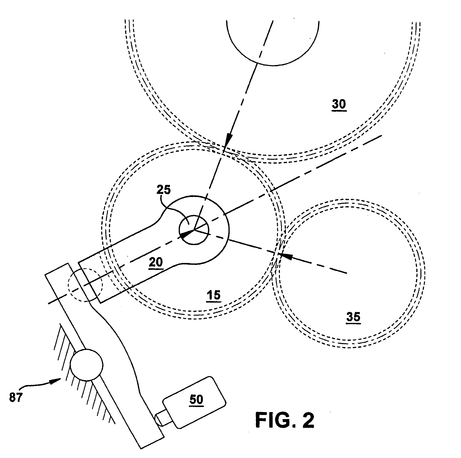
[0024] Referring now to the drawings, which show several embodiments of the invention only for the purpose of illustration and not for purposes of limiting the same, an apparatus for controlling backlash generally comprises an intermediate gear capable of adjustably meshed engagement between a first driving gear and preferably also a second driven gear, and a body rotatably supporting the intermediate gear wherein the body is capable of movement supporting the intermediate gear's adjustably meshed engagement with the first gear and preferably also the second gear.

[0025] While the present invention can be utilized to minimize noise in numerous gearing relationships, the preferred embodiment utilizes the invention with balance shafts used in automotive applications. A common problem associated with balance shafts is a noise known as “gear rattle” generally occurring at engine idle. Gear rattle occurs when the teeth of the balance shaft timing gears lose contact then re-establish cont...


PUM


Abstract

An apparatus for controlling backlash comprising an intermediate gear capable of adjustable meshed engagement between a first driving gear and a second driven gear, and a body rotatably supporting the intermediate gear and capable of movement in a direction that reduces the center distance between the intermediate gear and either the first gear, the second gear, or both. The movement of the body utilizes both a resilient urging and a hysteretic damping to supply appropriately light resilient biasing while being fortified against rapid retraction or repulsion.

Description

CROSS-REFERENCE TO RELATED APPLICATIONS [0001] This application claims priority from U.S. Provisional Patent Application No. 60 / 694,352 filed on Jun. 27, 2005, which is hereby incorporated by reference.BACKGROUND [0002] Balance shafts which are utilized to offset the cyclic shaking forces of rotating and reciprocating engine masses are required to maintain substantially fixed angular timing relationships with the engine's crankshaft. Chain drives and gearsets are both capable of this functionality, but both introduce acoustic emission issues when trying to do the job alone. Toothed belt drives are feasible but are generally unsuited to application requirements. [0003]“Chain Alone” Challenges—Chain drive systems having the automatic tensioning devices customarily needed to accommodate a lifetime of component wear can quite comfortably manage the operating center distance (hereafter “center distance”) variations that challenge gearsets, but carry acoustic emission issues of their own....

Claims


Application Information

Patent Timeline
Patent Type & Authority Applications(United States)
IPC IPC(8): F16H55/18
CPCF16H57/12Y10T74/19619Y10T74/19623F16H2057/126
Inventor CHEVALIER, STEVEN J.KILLION, DAVID L.
Owner METALDYNE BSM
Learn More