Breech-block system for a firearm

a technology of a breech block and a firearm, which is applied in the direction of weapons, shoulder-fired small arms, ammunition loading, etc., can solve the problems of user injury, inability to guarantee, and require corresponding structural and technical effort, and achieve reliable and precise function.

Active Publication Date: 2007-01-18
SPIELBERGER PETER
View PDF10 Cites 24 Cited by
  • Summary
  • Abstract
  • Description
  • Claims
  • Application Information

AI Technical Summary

Benefits of technology

[0010] The object of the present invention was therefore to provide a breech system of the type described in the preamble, which is provided by a simple arrang

Problems solved by technology

The second version requires corresponding additional structural and technical effort, whereby with long-barreled weapons the delay is usually achieved by means of tapping the gas pressure in the barrel.
The main disadvantage lies in the gas holes themselves, since if they become blocked this can lead in the simplest situation to malfunction, and in the worst case to the user being injured.
The disadvantage with this arrangement is the moving barrel, with which it cannot be guaranteed that it will be in exactly the same position again after each shot (in relation to the sight, which is secured to the retractor or slide).
A further disadvantage is the relatively high mass of the moving parts (480 g for the Colt M1911), from which the user acquires the subjective feel of the recoil and which makes the rapid repetition of aimed shots one after another difficult or even technically impossible (cadence).
The barrel itself is movable, however, so that, because of the play induced by manufacturing technology, it can never be ensured that the barrel, afte

Method used


Image

  • Breech-block system for a firearm
  • Breech-block system for a firearm
  • Breech-block system for a firearm

Examples


Embodiment Construction

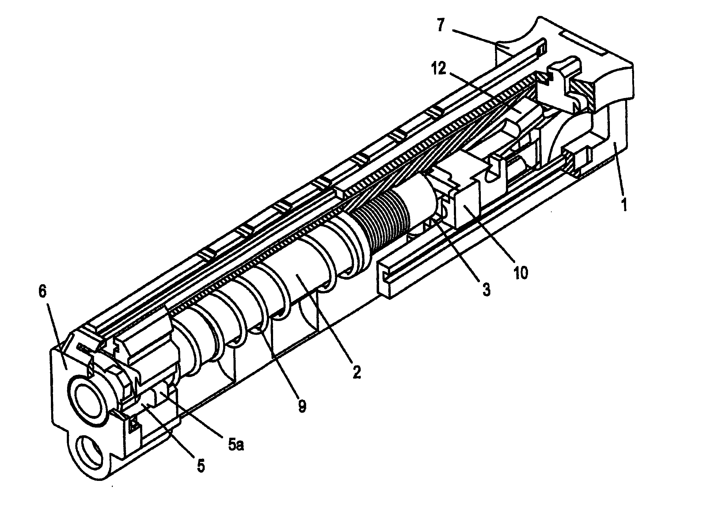
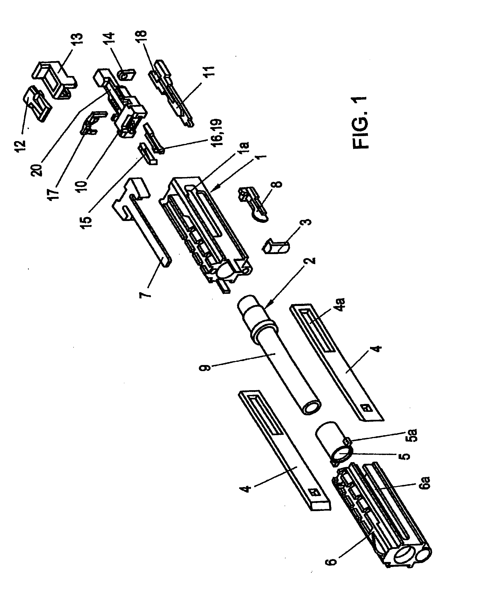
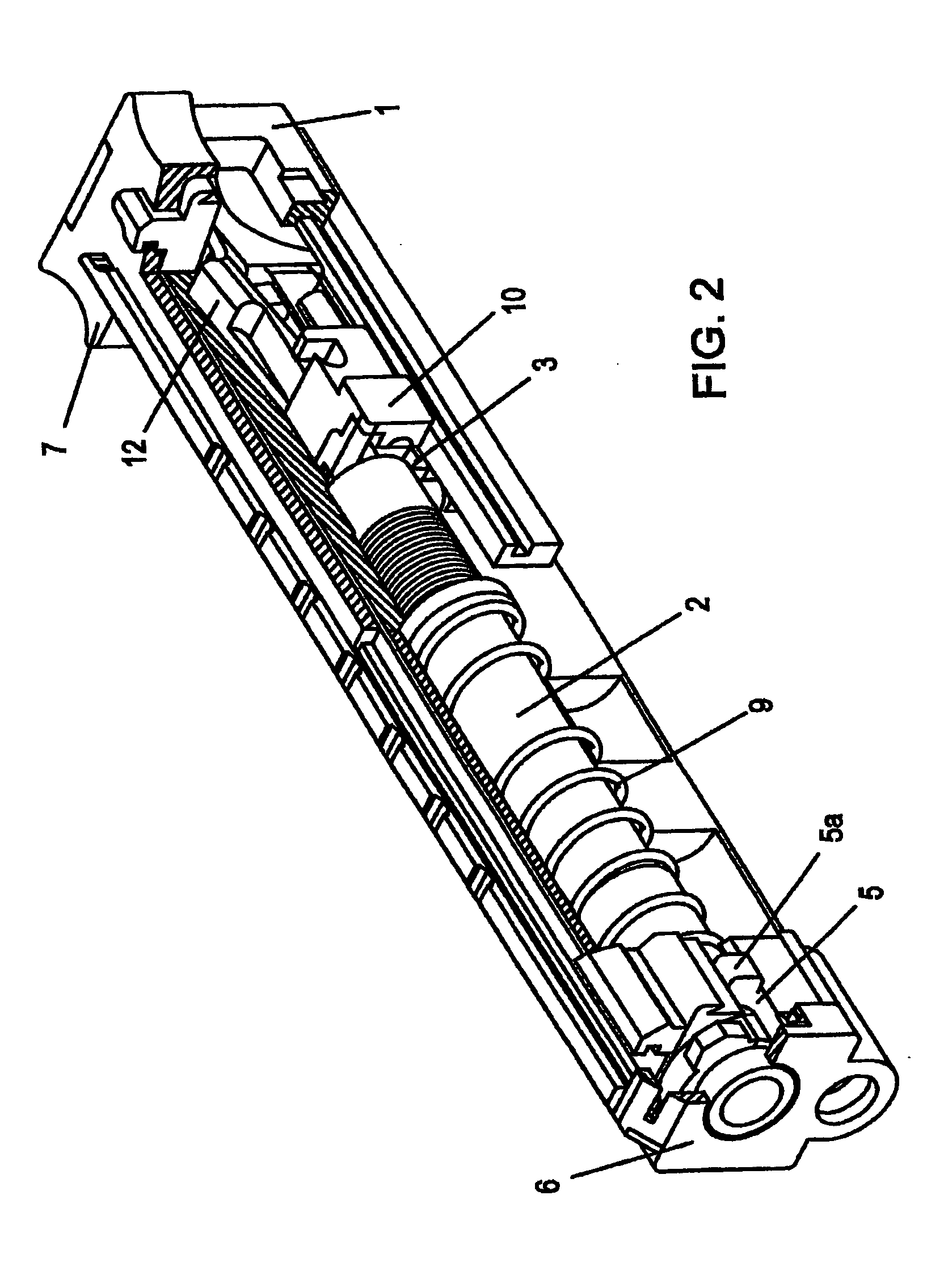
[0028] The central part of the system is the barrel block 1, into which the barrel 2 is screwed, and is therefore only fixed at this screw insertion point. As a result, high shot precision is guaranteed, since a rigid unit is formed from the barrel block 1 which also allows for the optimum mounting or integration of a sight, and from the rigid barrel 2, without other moving parts, or parts which change their position relative to one another while the shot is discharged. It is further of advantage that convenient manufacturing tolerances can be used for all moving parts. A ramp 3 is also inserted as a separate component between the barrel 2 and the barrel block 1. By means of this replaceable ramp, which can be selected in accordance with the ammunition used, the cartridge is introduced into the cartridge chamber of the rigid barrel 2. This ramp 3 is a critical part with all self-loading weapons systems, and is usually a part of the barrel. Different shapes of projectile rounds, howe...


PUM


Abstract

A breech system for a firearm exhibits a breech which can be locked in its movement in the barrel block by at least one locking element, which is pressed against the rear end of the barrel by means of a breech spring surrounding the rigid barrel of the weapon, the barrel being enclosed with the exception of the front and rear apertures, whereby the breech spring is supported at the rear section of the barrel and at least one link element subjected to tension connects the front end of the breech spring and the breech. In order to guarantee precise function and in a manner which is safe for the user, by means of a simple arrangement which is reproducible in manufacture, a purely mechanical delay element is inserted in the link between the breech (10) and the breech spring (9).

Description

BACKGROUND THE INVENTION [0001] The invention relates to a breech system for a firearm, with a breech capable of being locked in its movement in the barrel block by means of at least one locking element, which is brought into contact against the rear end of the barrel by means of a breech spring, whereby the breech spring is supported at the rear section of the barrel by at least one connection element, subjected to tension. [0002] A distinction is made between the following types of the breech system for automatic and semi-automatic pistols, rifles, machine pistols, and carbines: [0003] The pure mass breech, i.e. the relatively small mass of the projectile round is opposed by a correspondingly high mass of the breech (the breech must not have moved any further before the round has left the barrel than the length of the cartridge case, or the delayed mass breech, i.e. in addition to the interplay of the masses, a rigid or semi-rigid breech is used, which restrains the movement of th...

Claims


Application Information

Patent Timeline
IPC IPC(8): F41A3/86F41A5/12
CPCF41A5/12F41A3/40F41A9/55
Inventor SPIELBERGER, PETER
Owner SPIELBERGER PETER
Why Eureka
Try Eureka