
Electric energy generating modules with a two-dimensional profile and method of fabricating the same

a technology of electric energy generating modules and profiles, applied in photovoltaic energy generation, sustainable buildings, photovoltaic energy generation, etc., can solve the problems of reducing the efficiency of the connection process, requiring expensive press equipment, and affecting the aesthetics of the building or other structure, so as to reduce the efficiency loss of the shade of the profiled parts of the module on the other parts of the modul

Inactive Publication Date: 2007-01-18
VHF TECH
View PDF7 Cites 73 Cited by
  • Summary
  • Abstract
  • Description
  • Claims
  • Application Information

AI Technical Summary

Benefits of technology

[0013] The present invention relates to an electric energy generating module (such as a PV module) that is particularly well-suited for mounting and integration in a location (such as the facade or roof of a building) where a non-flat physical surface is either present or desired. This is accomplished by shaping the module so that the module takes on a desired two dimensional profile to match a non-flat surface or a non-flat architectural element. The present invention further relates to a method of fabricating such an electric energy generating module. The invention also relates to a module in which the efficiency losses due to shades by profiled portions of the module on other parts of the module are reduced.
[0015] The electric energy generating film comprises a plurality of strip-shaped cells electrically connected with one another. The longitudinal direction of each strip-shaped cell extends in parallel to a plane defining the two dimensional profile. Thus, shading on all serially connected strips is identical or at least comparable, and the efficiency of the module is not reduced by shading losses that arise when cells with different currents are connected in series.

Problems solved by technology

However, more recently, it has become common for modules of much thinner solar cell films to be monolithically deposited onto low-cost substrates (such as glass or plastic) using well-known semiconductor manufacturing techniques.
Moreover, the use of flat PV modules on uneven surfaces is often detrimental to the aesthetic look of a building or other structure.
Shaping and bending of the module is thus performed by application of a substantial pressure only, requiring an expensive press equipment.
The connection process is tedious and expensive; there is a need for a continuous fabrication method.
As a result, the efficiency of the resulting module is greatly reduced by high shading losses in some cells.
Bending requires a high pressure and expensive equipment, and measures are required to prevent damage to the photovoltaic layer.
However, most flexible PV modules remain less durable and more fragile than their rigid counterparts making them less suitable for use in architectural applications where they are exposed to weather and / or other environmental conditions.
Furthermore, the shaping and mounting of each flexible PV module so that its profile matches the desired profile of the roofing elements remains a relatively laborious process.

Method used


Image

  • Electric energy generating modules with a two-dimensional profile and method of fabricating the same
  • Electric energy generating modules with a two-dimensional profile and method of fabricating the same
  • Electric energy generating modules with a two-dimensional profile and method of fabricating the same

Examples


Embodiment Construction

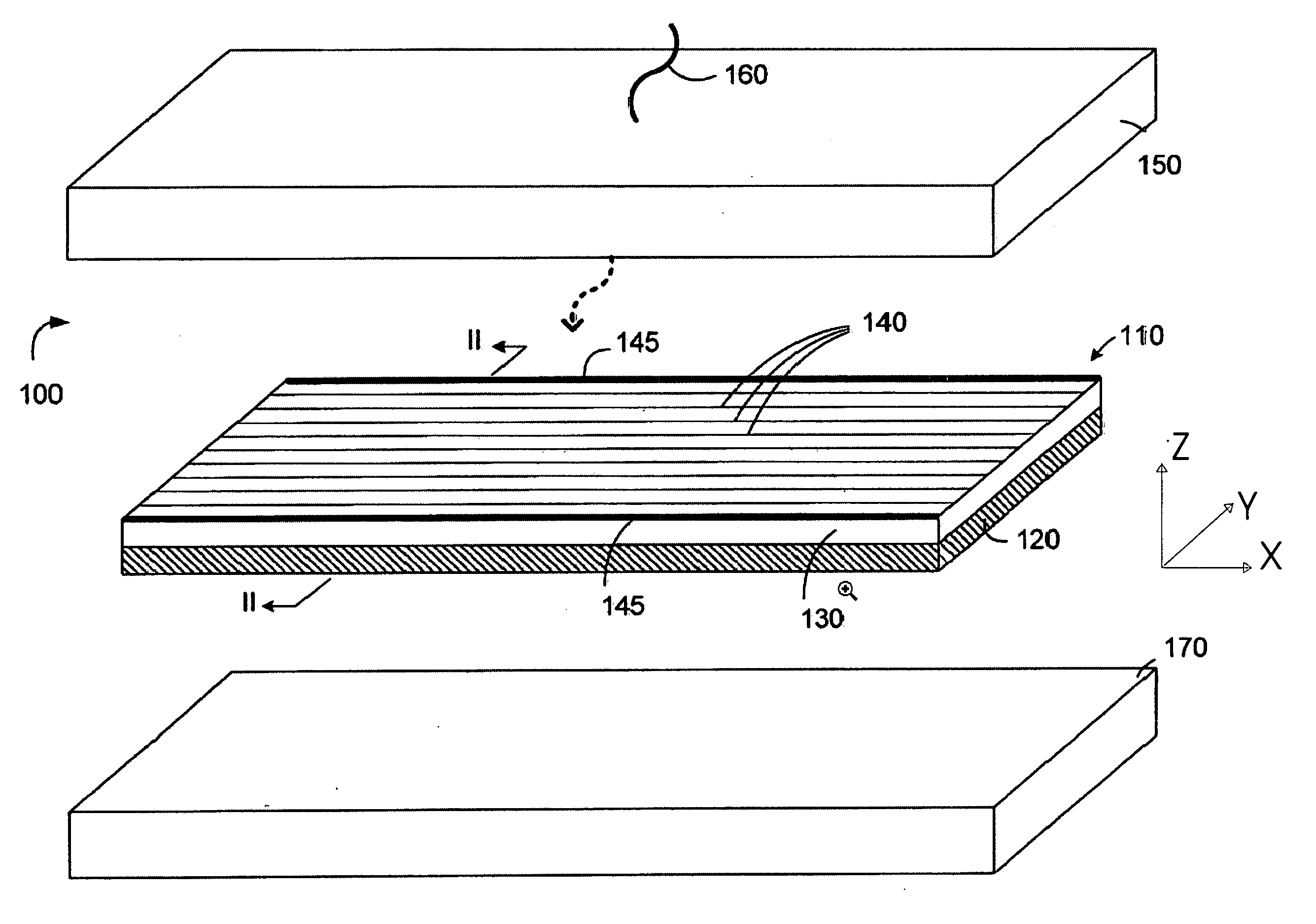
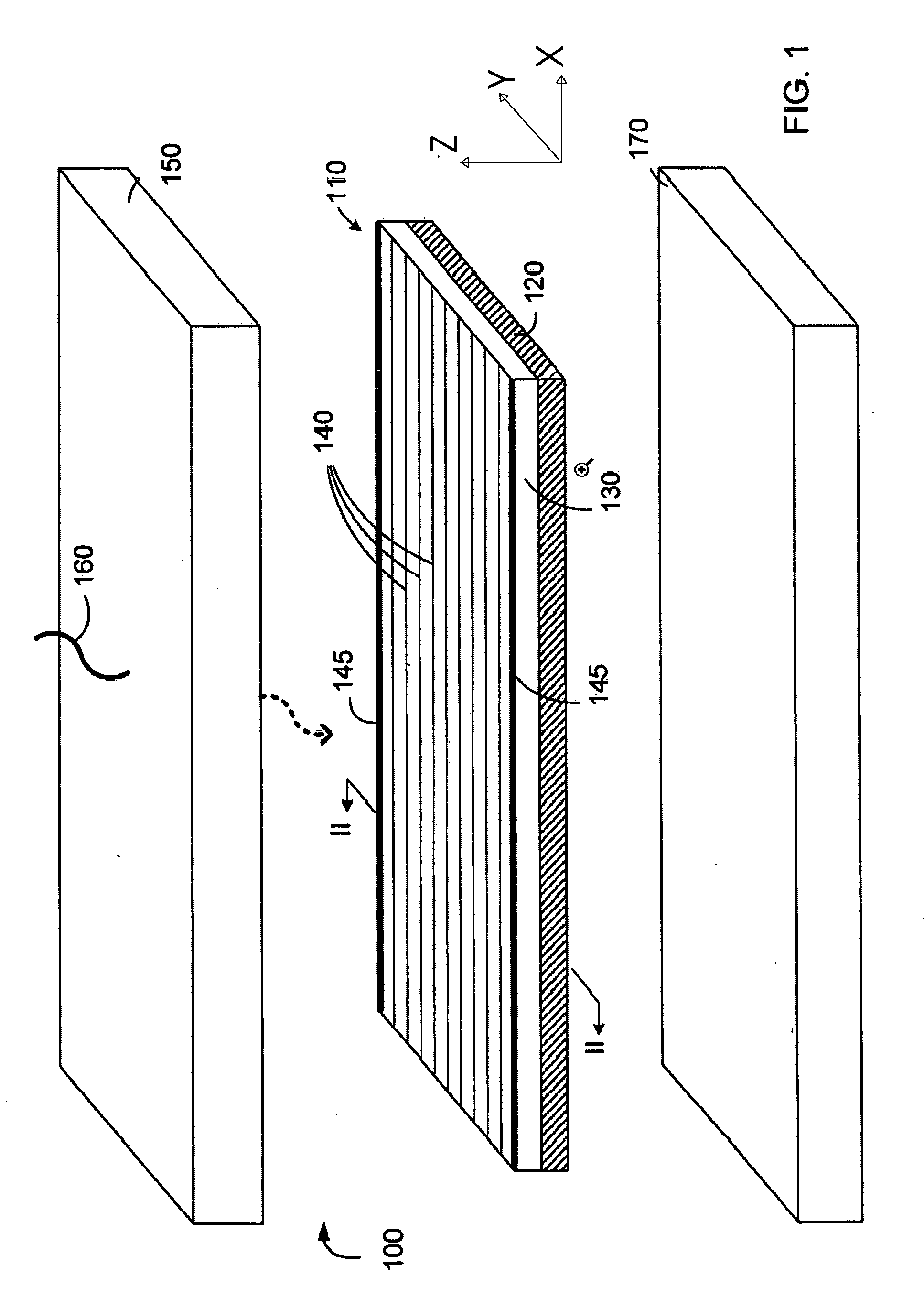
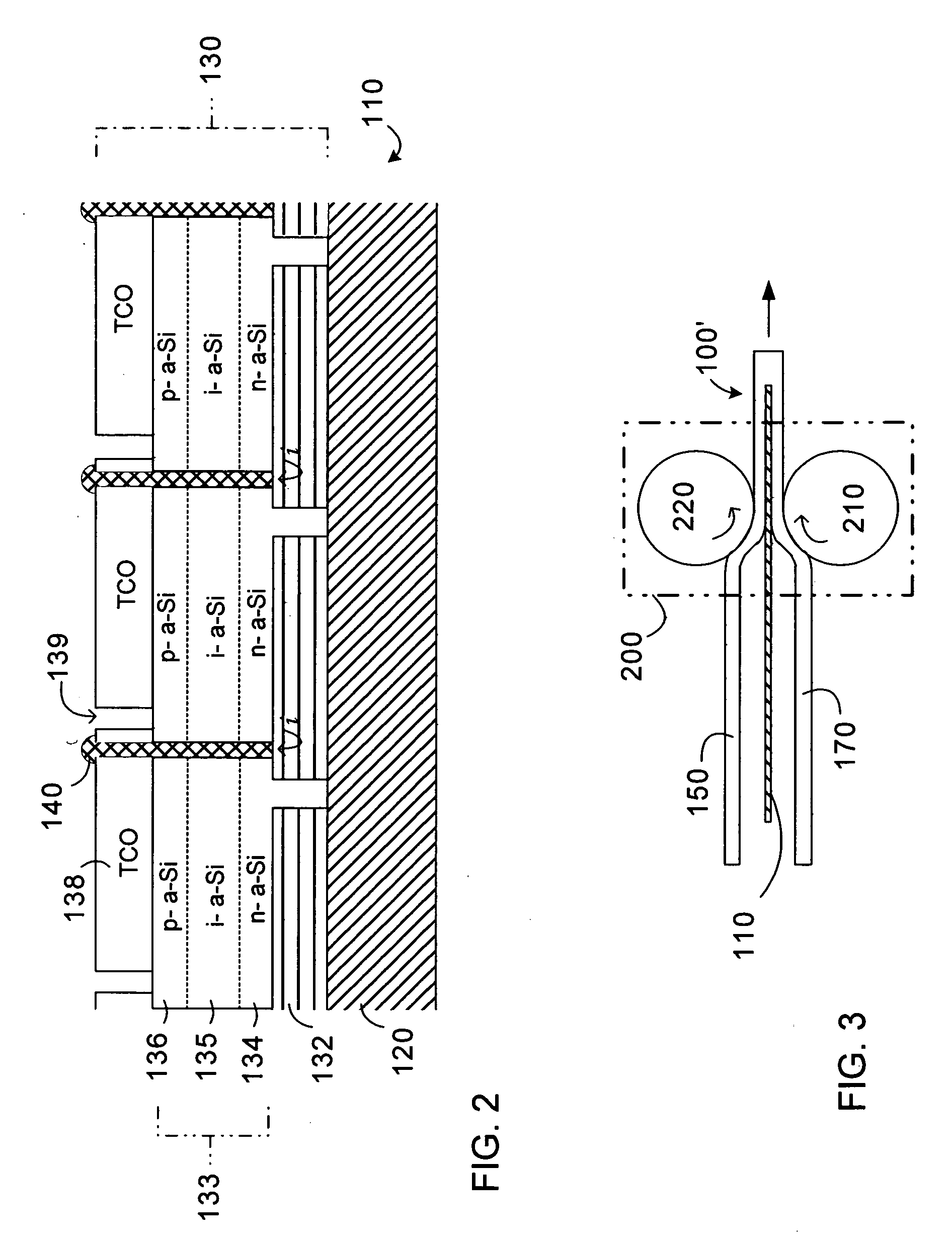
[0026] In accordance with a preferred embodiment of the present invention, FIG. 1 is an exploded view showing the different films (i.e., layers) within a PV module 100, prior to the module undergoing a bonding step. While the present invention can also be applied to other types of electrical energy generating films and modules, it is particularly suited to the PV field, and as a result PV applications are referred to herein. This is in no way intended to limit the scope of the present invention to other suitable types of electrical energy generating films and modules such as, for example, a hybrid thermophotovoltaic (TPV) film.

[0027] As shown in FIG. 1, PV module 100 is formed from a thin flexible PV film 110, a sheet of a top encapsulant material 150, and a sheet of a bottom encapsulant material 170. Although shown as flat (i.e., with a one-dimensional profile when viewed from the side), it will be appreciated that flexible PV film 110 is capable of adopting various 2-D profiles i...


PUM


Abstract

An electric energy generating module is shaped to take on a desired two dimensional profile to match a non-flat surface or architectural element such as corrugated roofing. The module includes an electric energy generating film sealed between a top layer of encapsulant material and a bottom layer of encapsulant material. The type and quantity of the encapsulant materials are such that the shape of the encapsulant materials can be altered when a high temperature and / or pressure is applied to the module, but where the encapsulant materials provide a rigid structure around the electric energy generating film under ordinary (i.e., naturally occurring) temperature and pressure conditions. The module can therefore be shaped by applying a suitable pressure and / or a high temperature but, once placed under ordinary temperature and pressure conditions, the module has a rigid structure.

Description

REFERENCE DATA [0001] This application is a continuation of international PCT application 2005WO-EP51214 (WO05091379) filed on Mar. 16, 2005 and which claims priority of the U.S. provisional application US2004-553380 filed on Mar. 16, 2004, the contents whereof are hereby incorporated by reference.FIELD OF THE INVENTION [0002] The present invention relates to the field of electric energy generating modules, such as solar cell modules using photovoltaic films. More particularly, the present invention relates to electric energy generating modules that are especially suitable for roofing and other architectural applications having non-flat surfaces. The present invention further relates to a method of fabricating such modules. DESCRIPTION OF RELATED ART [0003] Energy harvested from solar cell technology is being increasingly exploited as a valuable, renewable and generally ubiquitous resource. The solar cell industry continues to grow as the technology employed becomes more energy effi...

Claims


Application Information

Patent Timeline
Patent Type & Authority Applications(United States)
IPC IPC(8): H02N6/00
CPCH01L31/03921H01L31/048H01L31/046Y02E10/50Y02B10/12H01L31/03926H02S20/23H02S20/25H02S20/26Y02B10/10
Inventor FISCHER, DIEGOCLOSSET, ALEXANDREZIEGLER, YVAN
Owner VHF TECH
Learn More