
System and methods for glass recycling at a beneficiator

a technology of beneficiator and glass, applied in glass recycling, gas current separation, centrifuges, etc., can solve the problems of low economic viability, low efficiency, laborious and costly current manual and automated sorting methods,

Inactive Publication Date: 2007-01-18
RE COMMUNITY HLDG II INC
View PDF25 Cites 15 Cited by
  • Summary
  • Abstract
  • Description
  • Claims
  • Application Information

AI Technical Summary

Benefits of technology

"The invention provides systems and methods for recycling mixed color glass and ceramic materials from waste material. The systems include a feed hopper for receiving waste material, a ferrous separator for removing ferrous material, a ceramic detector and separator for removing ceramic material, and an output hopper for receiving the mixed color cullet. The methods involve separating the mixed color cullet from contaminants, such as ceramic material and ferrous material, and adding it to a single color glass stream to produce a second mixed color cullet. The invention improves the efficiency and productivity of a beneficiator by separating the mixed color cullet from the contaminants and providing it to a glass manufacturer. The technical effects of the invention include recycling mixed color glass and ceramic materials from waste material and improving the efficiency of the recycling process."

Problems solved by technology

Cost-effective recycling of materials, such as glass, has become an increasingly important issue to many businesses due, for example, to ever increasing legislative mandates at the federal, state and local levels, and the associated cost of complying therewith.
In a recycling process, an entity such as a beneficiator can face several significant challenges, particularly with regard to color sorting and recovery of sufficiently clean glass.
A conventional beneficiator usually processes one color of glass at a time, particularly when automated optical sorting is performed, generally due to the added cost associated with providing the equipment and / or labor that would enable two or more colors of glass to be simultaneously color sorted.
The second line often; however, is inactive, as the line must wait for the first line to finish processing before receiving the glass stream.
Current manual and automated sorting methods are labor intensive and costly.
Moreover, color sorting of mixed cullet is generally not economically viable.
The beneficiator may also blend mixed cullet into the color sorted glass, but is limited by the amount of cullet that can be blended into the separated glass because separated glass colors must generally ship with, for example, a maximum 5% color contamination.

Method used


Image

  • System and methods for glass recycling at a beneficiator
  • System and methods for glass recycling at a beneficiator
  • System and methods for glass recycling at a beneficiator

Examples


Embodiment Construction

[0018] The inventors have determined that it would be advantageous to simplify the glass sorting and cleaning process that can be used by a beneficiator; it would be advantageous to enable a beneficiator to recycle glass without having to sort the glass by color; it would be advantageous to enable a beneficiator to process mixed cullet as well as single-colored glass; and it would be advantageous to enable a beneficiator to combine increasing quantities of mixed cullet with a color sorted glass stream; and it would be advantageous to enable a beneficiator to supply glass plants with cullet that can be used in conjunction with, for example, the de-coloring / coloring technology described in U.S. Pat. Nos. 5,718,737 and 6,230,521, the disclosures of which are incorporated by reference in their entirety.

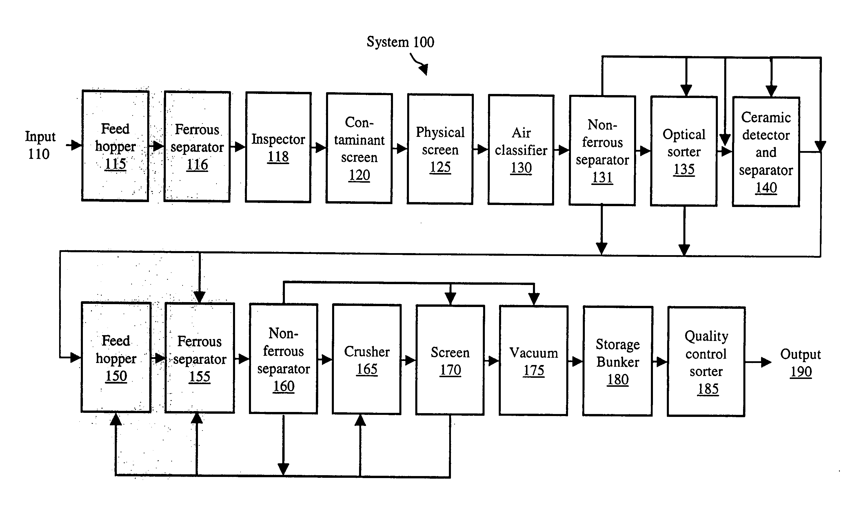
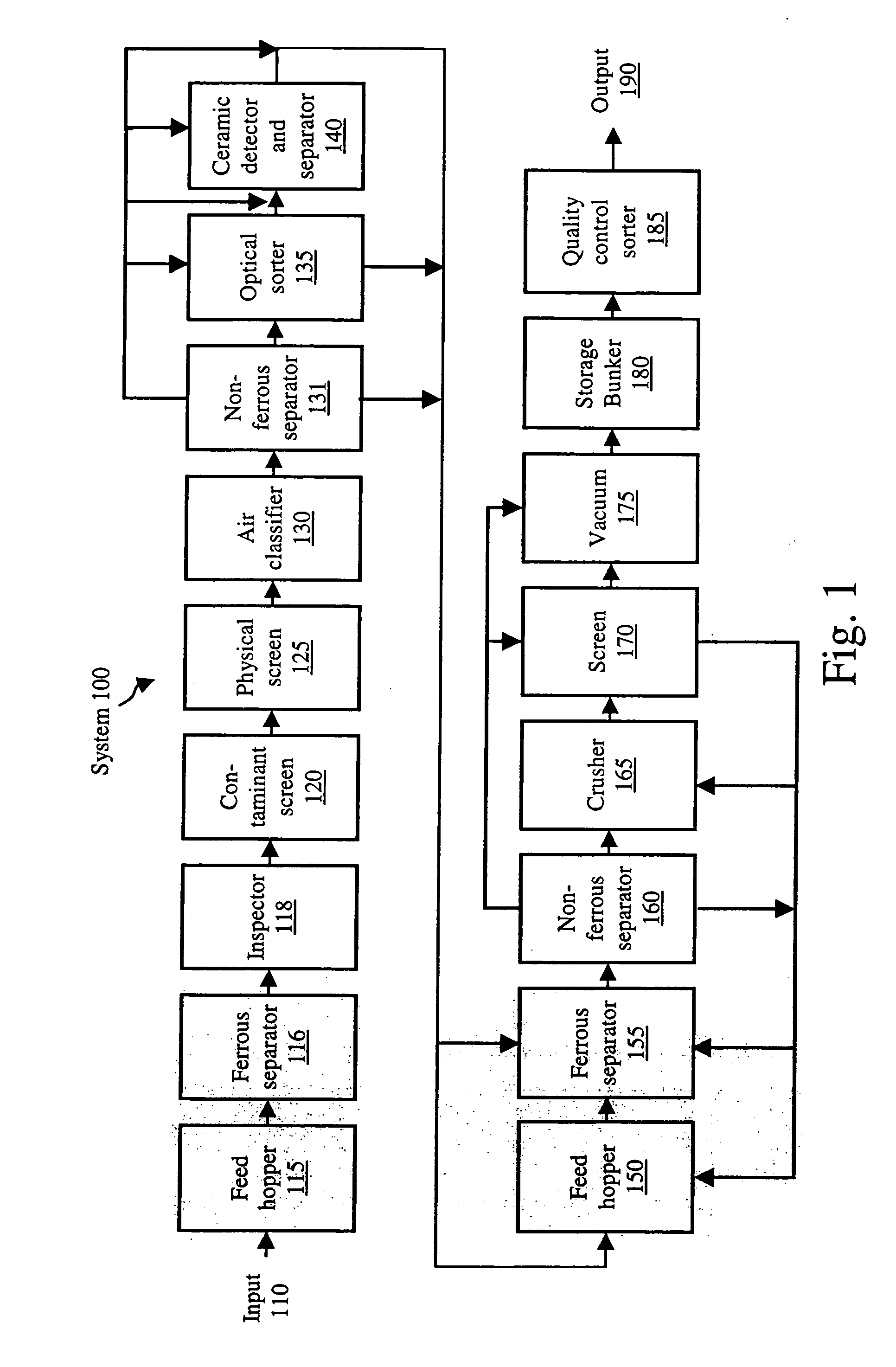
[0019]FIG. 1, generally at 100, illustrates a block diagram of an embodiment of an exemplary beneficiator glass recycling system in accordance with the invention. The method of FIG. 1 ut...


PUM


Abstract

The invention provides systems and methods for obtaining recycled mixed cullet at a beneficiator. The recycled mixed cullet can be used by glass plants to make new glass articles, such as beverage bottles.

Description

RELATED APPLICATIONS [0001] This application claims priority under § 119 to U.S. application Ser. No. 60 / 534,688 filed Jan. 8, 2004, and to U.S. application Ser. No. 60 / 520,311 filed Nov. 17, 2003, the disclosures of which are incorporated by reference herein.FIELD OF THE INVENTION [0002] The invention provides systems and methods for recycling glass at a beneficiator. BACKGROUND OF THE INVENTION [0003] Cost-effective recycling of materials, such as glass, has become an increasingly important issue to many businesses due, for example, to ever increasing legislative mandates at the federal, state and local levels, and the associated cost of complying therewith. In a recycling process, an entity such as a beneficiator can face several significant challenges, particularly with regard to color sorting and recovery of sufficiently clean glass. [0004] A beneficiator is an entity, within an overall glass recycling system, that typically receives glass from one or more material recovery fac...

Claims


Application Information

Patent Timeline
Patent Type & Authority Applications(United States)
IPC IPC(8): B03B7/00B03B9/06B07B9/00
CPCB07B9/00B03B9/062Y02W30/60
Inventor BOHLIG, JAMES W.DUFFY, SEAN P.
Owner RE COMMUNITY HLDG II INC
Learn More