Eureka AIR delivers breakthrough ideas for toughest innovation challenges, trusted by R&D personnel around the world.

Fast, simple radiation detector for responders

a simple, fast technology, applied in the field of radiological detectors, can solve the problems of increased personnel and training, increased cost of detection equipment, and threat to the u.s. homeland security, and achieve the effect of avoiding false-positive responses and low cos

Inactive Publication Date: 2007-01-18
TESTARDI LOUIS RICHARD
View PDF5 Cites 26 Cited by
  • Summary
  • Abstract
  • Description
  • Claims
  • Application Information

AI Technical Summary

Benefits of technology

[0010] It is one object of the invention to provide a radiation detection system and method which is sensitive, continuously tested, and hard to cheat.
[0012] It is a further additional or alternative object of the invention to provide a radiation detection system and method which is low cost and which utilizes currently available components.
[0013] It is a still further additional or alternative object of the invention to provide a radiation detection system and method which avoids false-positive responses.
[0014] It is a still further additional or alternative object of the invention to provide a radiation detection system and method which leads to no (or minimal) delay for radiation inspection.

Problems solved by technology

This can make them a threat to U.S. homeland security.
Shortcomings of current baggage, package, container, and portal radiation detection methods are i) the cost of detection equipment, ii) the cost of added personnel and training, iii) the detection delays for baggage, packages and passengers, iv) the possibility that detection can be cheated, and v) the possibility of travel delays or even travel cancellations due to false-positive radiation detection signals.
In addition, there is the possibility of catastrophic radiation exposure in the U.S. homeland, whether due to terrorism, war, nuclear accidents, or other man-made or natural causes.

Method used


Image

  • Fast, simple radiation detector for responders
  • Fast, simple radiation detector for responders
  • Fast, simple radiation detector for responders

Examples


second modified embodiment

[0066] Referring now to FIGS. 10a and 10b, there is shown a small scintillating fiber (small SF) radiation detector for homeland security according to the invention. Except as described below, the structure of the second modified scintillating fiber radiation detector for homeland security 10″ is substantially identical to the structure of the scintillating fiber radiation detector for homeland security 10 shown in FIGS. 1 to 4, and for the sake of brevity, the details of that preferred embodiment are incorporated by reference into the second modified embodiment.

[0067] In the second modified embodiment of FIGS. 10a and 10b, the tube 30 and scintillating fiber 60 each have lengths which are relatively short (e.g. between about ½ inch and about 8 inches) The tube 30 is a substantially rigid structure, and both the scintillating fiber 60 and the PMT 20 are mounted to the tube 30 (e.g. directly, or indirectly by means of the adapter plate 70) in a substantially relatively immovable mann...


PUM


Abstract

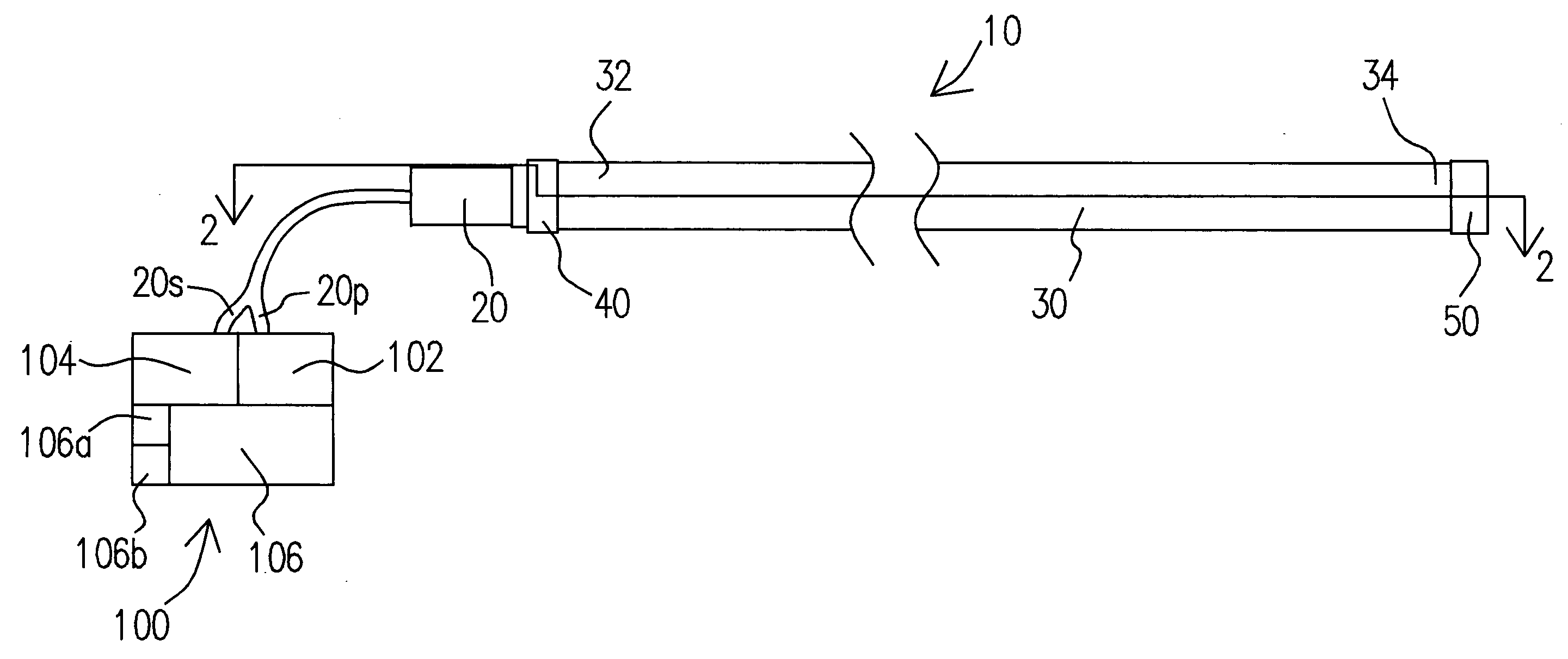
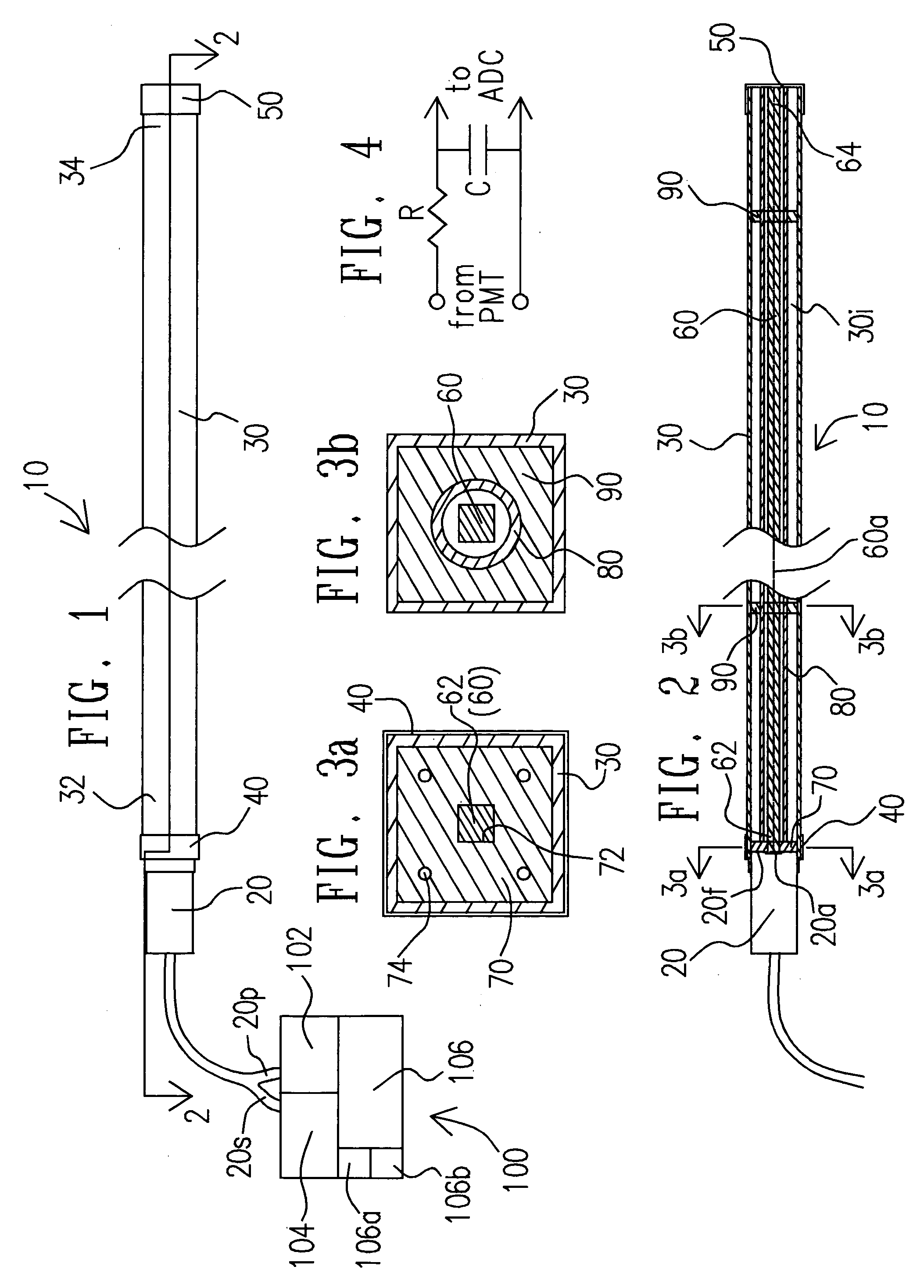
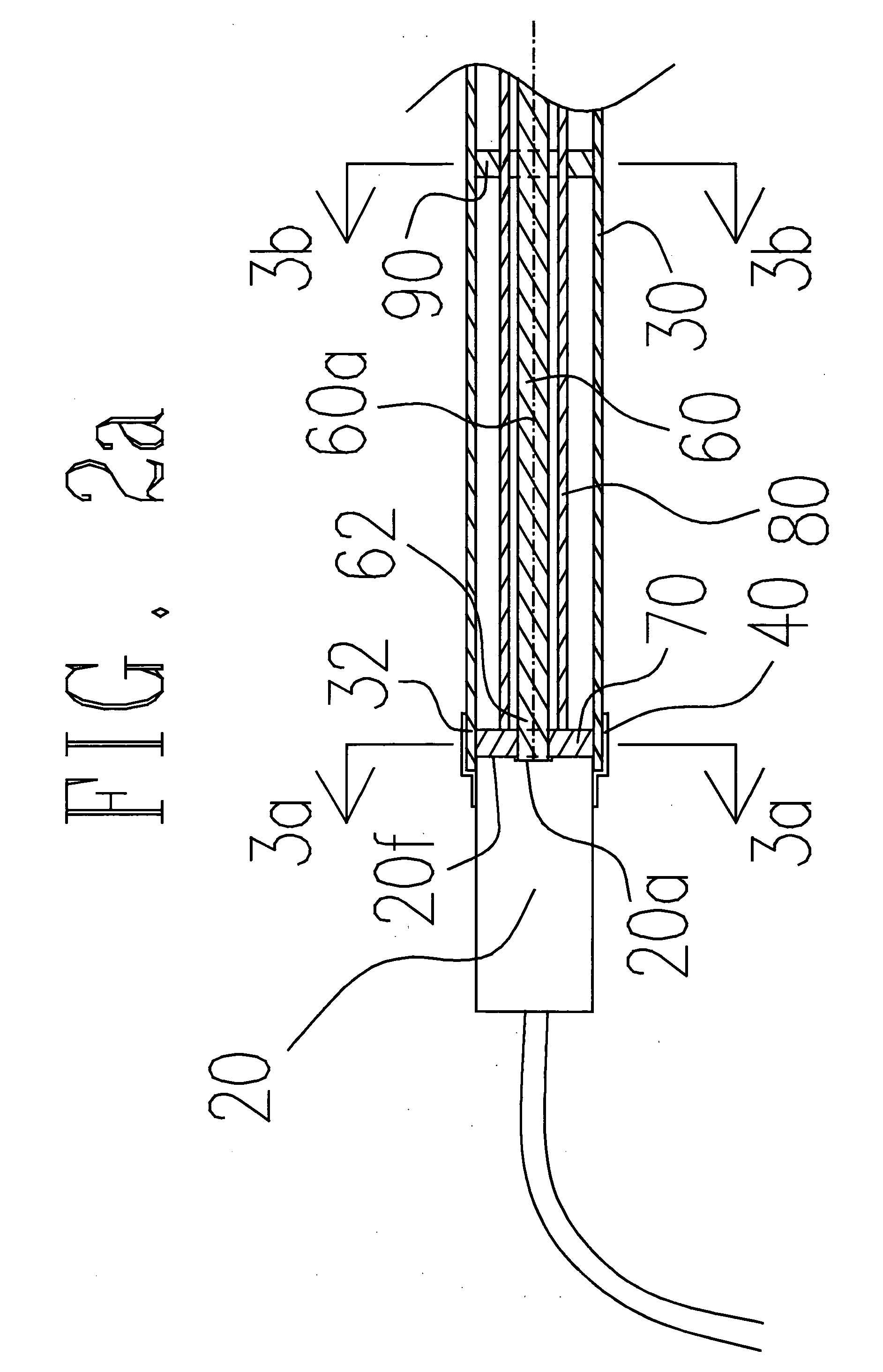
A radiation detection device, system, and method for use in homeland security is disclosed. The device is portable and includes a photomultiplier tube (PMT) connected to an end of a substantially rigid thin-walled aluminum tube. Inside the aluminum tube, a substantially straight scintillating fiber is disposed (so as to be shielded from ambient light), and an end of the scintillating fiber is optically coupled to the PMT. A voltage output signal from the PMT is signal-processed with a filter to remove high-frequency noise (which may arise from solar radiation spikes) and fed to a voltage-responsive alarm or signalling device. The portable device is employed, for example, by responders to nuclear incidents and is packaged as a small wearable hands-free and eyes-free unit with a continuous in-use self-testing feature.

Description

CROSS-REFERENCE TO RELATED APPLICATIONS [0001] This application is a continuation-in-part of U.S. patent application Ser. No. 10 / 766,943, filed on Jan. 30, 2004, entitled “Fast, Simple Radiation Detector”, the contents of which is incorporated by reference herein.BACKGROUND OF THE INVENTION [0002] 1. Field of the Invention [0003] The present invention pertains to the field of radiation detectors which employ scintillating fibers. More particularly, the present invention pertains to the field of scintillating fiber radiation detectors which are used for homeland security. [0004] 2. Description of the Related Art [0005] There is the possibility that radioactive materials, to be used in ‘Dirty Bombs’, can be sent to the U.S. from a foreign location. This can make them a threat to U.S. homeland security. Likely radio-nuclides for terrorist use include Cesium-137 and Cobalt-60 because of their (respective) penetrating radiation quantum energy (0.7 & 1.3 MeV gamma rays), long radiation ha...

Claims


Application Information

Patent Timeline
IPC IPC(8): G01T1/20
CPCG01T1/161G01T7/00G01T1/201
Inventor TESTARDI, LOUIS RICHARD
Owner TESTARDI LOUIS RICHARD
Why Eureka
Eureka Blog
Learn More