Framework that maximizes the usage of testhead resources in in-circuit test system

a test system and testhead technology, applied in the direction of electronic circuit testing, measurement devices, instruments, etc., can solve the problems of insufficient utilization of testhead resources, and current software that requires manual intervention, so as to maximize the use of testheads

Inactive Publication Date: 2007-01-18
AGILENT TECH INC
View PDF9 Cites 15 Cited by
  • Summary
  • Abstract
  • Description
  • Claims
  • Application Information

AI Technical Summary

Benefits of technology

[0006] The present invention is a method and apparatus for maximizing the usage of a testhead of an in-circuit tester in a manufacturing environment. A testhead execution supervisor interfaces between a testhead controller and a graphical user interface used to enter manual tests. The testhead execution supervisor adds tests to be submitted to the testhead to one or more queues according to a priority scheme. Tests may be submitted to the testhead execution supervisor both as manual tests entered via a graphical user interface and as automatically generated tests generated by an automatic debug module. The automatic debug module may automatically generate tests for execution by the testhead that are executed when the testhead is idle, for example when no higher priority manual tests are scheduled.

Problems solved by technology

With the improvements in speed and density of integrated circuits, the cost and complexities of designing and testing these integrated circuits has dramatically increased.
However, in order to execute any test, whether entered manually or generated automatically by tester software, current software requires manual intervention to schedule the execution of tests.
Regardless of the experience of the test engineer and conditions under which the engineer is working, which can vary widely and therefore result in differing solution times, this approach does not fully maximize usage of the in-circuit testhead.
In addition, upon completion of any given test, unless additional tests have been scheduled, the testhead is also left idle.

Method used


Image

  • Framework that maximizes the usage of testhead resources in in-circuit test system
  • Framework that maximizes the usage of testhead resources in in-circuit test system
  • Framework that maximizes the usage of testhead resources in in-circuit test system

Examples


Embodiment Construction

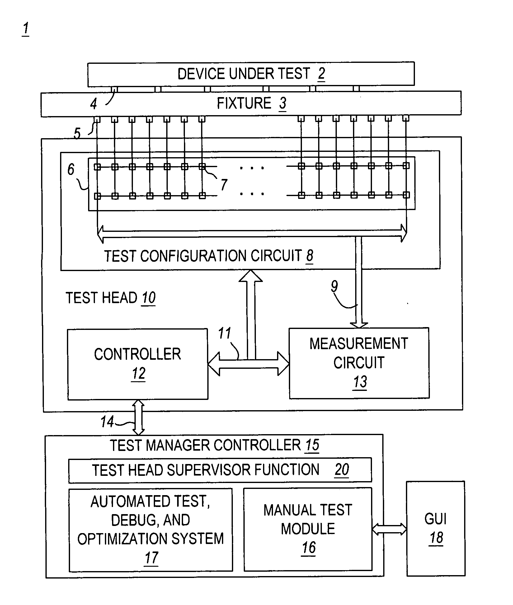
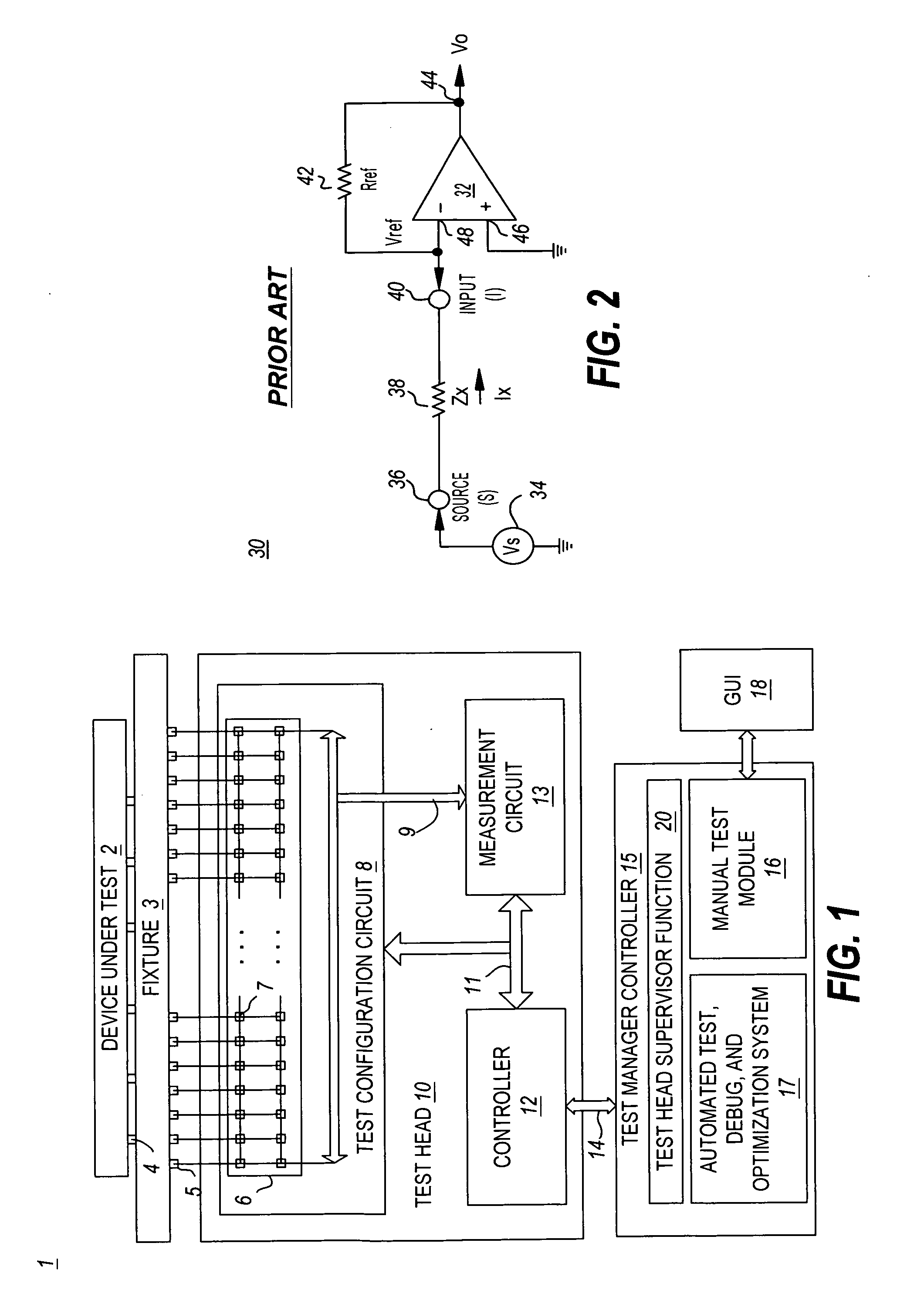
[0017] Turning now to the invention, FIG. 1 is a schematic block diagram of an automated test system 1 implemented in accordance with the invention. As illustrated, the test system 1 includes a test head 10 and a test manager controller 15. The controller 15 may be integrated with the test head 10 or execute separately from the test head 10, communicating with the test head 10 via a communication link 14 (as shown).

[0018] The test head 10 may support a fixture 3 on which a printed circuit board (PCB) containing or implementing a device under test (DUT) 2 is mounted. Fixture 3, for example a bed-of-nails fixture, is customized for each PCB layout and includes a plurality of probes 4 that electrically connect to nodes of the device under test 2 when the device under test 2 is properly seated on the fixture 3. Probes 4 are coupled via the fixture 3 to test head interface pins 5.

[0019] The test head 10 may include a test configuration circuit 8 configured with a programmably configura...


PUM


Abstract

A method and apparatus for maximizing the usage of a testhead of an in-circuit tester is presented. A testhead execution supervisor interfaces between a testhead controller and a graphical user interface used to enter manual tests. The testhead execution supervisor adds tests to be submitted to the testhead to one or more queues according to a priority scheme. Tests may be submitted to the testhead execution supervisor both as manual tests entered via the graphical user interface and as automatically generated tests generated by an automatic debug module. The automatic debug module may automatically generate tests for execution by the testhead that are executed when the testhead is idle, for example when no higher priority manual tests are scheduled.

Description

BACKGROUND OF THE INVENTION [0001] The increasing reliance upon computer systems to collect, process, and analyze data has led to the continuous improvement of the system assembly process and associated hardware. With the improvements in speed and density of integrated circuits, the cost and complexities of designing and testing these integrated circuits has dramatically increased. Currently, large complex industrial integrated circuit testers (commonly referred to in the industry as “Automated Test Equipment” or “ATE”) perform complex testing of integrated circuit devices, such as integrated circuits, printed circuit boards (PCBs), multi-chip modules (MCMs), System-on-Chip (SOC) devices, printed circuit assemblies (PCAs), etc. The tests that must be performed may include, among others, in-circuit test (ICT), functional test, and structural test, and are designed to verify proper structural, operational, and functional performance of the device under test (DUT). [0002] An example of...

Claims


Application Information

Patent Timeline
Patent Type & Authority Applications(United States)
IPC IPC(8): G01R31/28
CPCG01R31/2886G01R31/31723G01R31/31705G01R31/2894
Inventor LOH, AIK KOONWILLIAMS, ROYWAI, KEEN FUNG JASONLOW, CHEN NIJIN, YISHANG, REXTAN, TIAM HOCK JOSEPHWHANG, DANIEL Z.
Owner AGILENT TECH INC
Why Eureka
Try Eureka