Duty cycle correction device

Active Publication Date: 2007-01-18
SK HYNIX INC
View PDF7 Cites 14 Cited by
  • Summary
  • Abstract
  • Description
  • Claims
  • Application Information

AI Technical Summary

Benefits of technology

[0014] In addition, the duty detection unit detects a difference

Problems solved by technology

However, the conventional DCC device, which employs the delay circuit or the like in order to adjust the duty cycle of a

Method used


Image

  • Duty cycle correction device
  • Duty cycle correction device
  • Duty cycle correction device

Examples


Embodiment Construction

[0024] Hereinafter, a preferred embodiment of the present invention will be described with reference to the accompanying drawings. In the following description and drawings, the same reference numerals are used to designate the same or similar components, so repetition of the description on the same or similar components will be omitted.

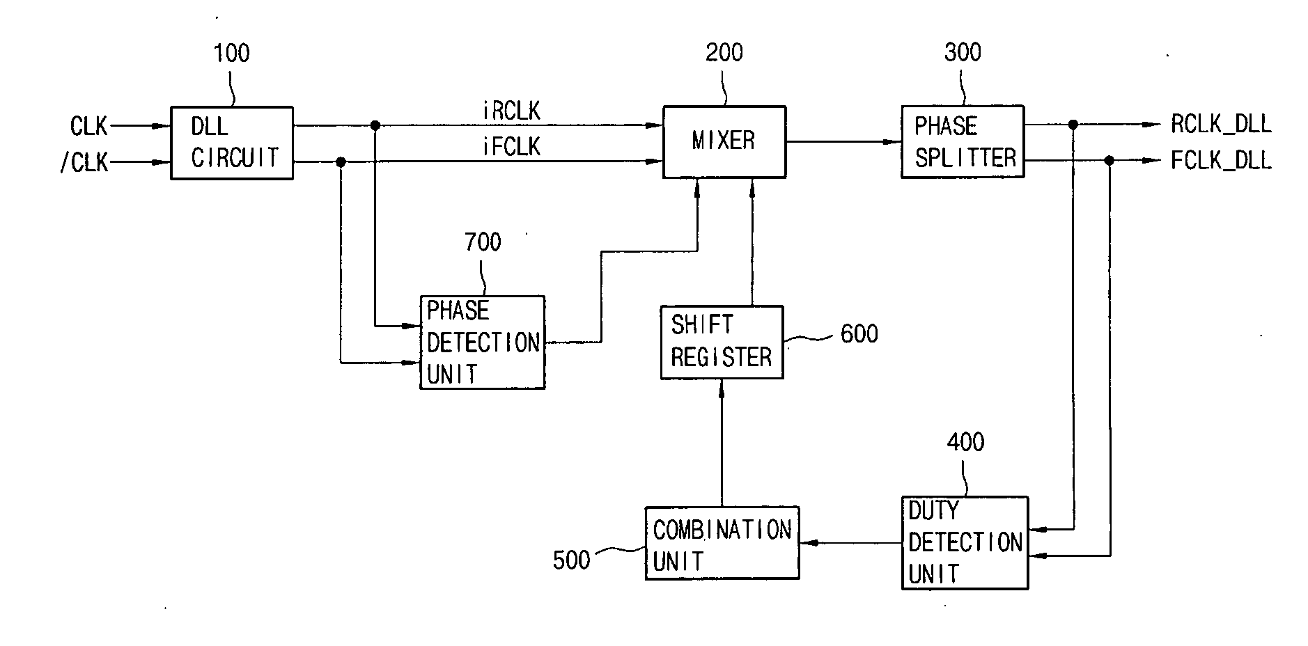
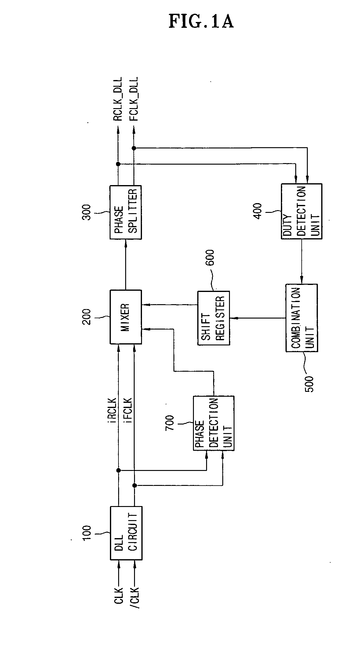
[0025]FIG. 1a is a view illustrating the structure of a duty cycle correction device according to an embodiment of the present invention.

[0026] As shown in FIG. 1a, the duty cycle correction device includes a mixer 200 for receiving signals “iRCLK” and “iFCLK” output from a delay locked loop (DLL) circuit 100, a phase splitter 300 for receiving an output signal of the mixer 200 and outputting signals “RCLK_DLL” and “FCLK_DLL” having a corrected duty-cycle, a duty detection unit 400 for detecting the duty cycles of the signals “RCLK_DLL” and “FCLK_DLL” output from the phase splitter 300, a combination unit 500 for receiving an output signal of the d...


PUM


Abstract

Disclosed is a duty cycle correction device for correcting a duty cycle of a clock signal output from a delay locked loop circuit. The duty cycle correction device includes a mixer for mixing phases of the first and second clock signals, thereby outputting a first signal, a phase splitter receiving the first signal and outputting a third clock signal, a duty detection unit receiving the third and fourth clock signals to detect a difference between duty cycles of the third and fourth clock signals, a combination unit for outputting a second signal, a shift register for outputting a first control signal, a phase detection unit receiving the first and second clock signals and outputting a second control signal representing a difference between duty cycles of the first and second clock signals. The mixer adjusts a mixing ratio by using the first and second control signals.

Description

BACKGROUND OF THE INVENTION [0001] 1. Field of the invention [0002] The present invention relates to a duty cycle correction device used for a semiconductor memory chip. More particularly, the present invention relates to a duty cycle correction device for correcting a duty cycle of a clock signal output from a delay locked loop (DLL) circuit by using a phase mixer. [0003] 2. Description of the Prior Art [0004] As generally known in the art, a DLL circuit is a clock generation device, which is accommodated in a synchronous memory device so as to compensate for skew between an external clock and an internal clock. Synchronous memory devices, such as DDR, DDR2, etc., control the timing for input / output operations in synchronization with an internal clock output from a DLL circuit. In the case of these synchronous memory devices, since data are input / output in synchronization with the rising and falling edges of an external clock, it is preferred if the duty cycle of an internal clock ...

Claims


Application Information

Patent Timeline
IPC IPC(8): H03K3/017
CPCH03L7/0812H03K5/1565G11C8/00G11C11/407
Inventor LEE, HYUN WOO
Owner SK HYNIX INC
Why Eureka
Try Eureka