Multiplex near-field microscopy with diffractive elements

a near-field microscopy and diffractive element technology, applied in the field of imaging methods and apparatuses, can solve the problems of only one point at a time, limited resolution by tip size, and surface alteration or tip damage,

Inactive Publication Date: 2007-01-18
THE BOARD OF TRUSTEES OF THE UNIV OF ILLINOIS
View PDF9 Cites 49 Cited by
  • Summary
  • Abstract
  • Description
  • Claims
  • Application Information

AI Technical Summary

Problems solved by technology

Unfortunately these methods require the sample to be placed in a vacuum, which is harmful for many biological samples, and subjects the sample to ionizing and heating radiation often damaging the sample.
While both STM and AFM have produced excellent atomic-scale images, they are slow because they require serial scanning of the surface, moreover, near-contact of the probe and surface can result in surface alteration or tip damage.
Unfortunately, these waves contain only information corresponding to features greater than one-half the wavelength of light on the surface.
This method likewise employs serial scanning techniques, and has a resolution limited by the tip size.
While the foregoing near-field methods have been able to achieve high-resolution images (of approximately 20 nm resolution or better), they suffer from other disadvantages.
This means that the acquisition occurs only one point at a time and is very slow.
Unfortunately, this means that the probe also collects less light, further decreasing available signal.

Method used


Image

  • Multiplex near-field microscopy with diffractive elements
  • Multiplex near-field microscopy with diffractive elements
  • Multiplex near-field microscopy with diffractive elements

Examples


Embodiment Construction

Fundamental Principles and Terminology

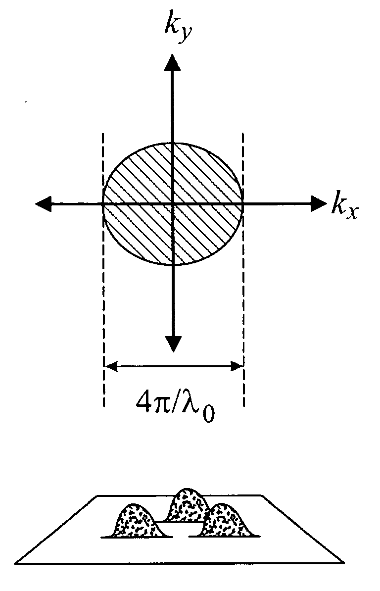
[0039] As background to a description of the principles underlying the present invention, of this new instrument, a standard imaging instrument is first considered. If we image with a standard microscope of a numerical aperture given by N, the minimum feature size that may be imaged is approximately λ0 / 2N, where λ0 is the illumination wavelength. (The numerical aperture refers to the sine of the opening half-angle (or the angular semiaperture) in the object space multiplied by the refractive index of the object space and is a measure of the light-gathering power of an optical system.)

[0040] The performance of imaging systems is also commonly understood in terms of spatial frequencies. A single spatial frequency can be visualized by a periodic sinusoidal pattern of parallel lines. The number of lines per unit length (perpendicular to the lines) is the spatial frequency. For example, a pattern of lines where each line is separated by 10 μm has ...


PUM


Abstract

A near-field microscope using one or more diffractive elements placed in the near-field of an object to be imaged. A diffractive covers the entire object, thus signal may thereby be gathered from the entire object, and advantageously increase the signal-to-noise ratio of the resulting image, as well as greatly improve the acquisition speed. Near-field microscopy overcomes the limitation of conventional microscopy in that subwavelength and nanometer-scale features can be imaged and measured without contact.

Description

[0001] This application claims priority from U.S. Provisional Patent Application Ser. No. 60 / 675,838, filed Apr. 28, 2005, which is incorporated herein by reference.[0002] This invention was developed with Government support under Contract Number F49620-03-1-0379 awarded by the United States Air Force Office of Scientific Research. The Government has certain rights in the invention.TECHNICAL FIELD AND BACKGROUND ART [0003] The present invention pertains to methods and apparatus for imaging at resolutions below that corresponding to the wavelength of illuminating radiation. [0004] The ability to resolve smaller and smaller features using microscopy has resulted in enormous gains in almost all branches of science and technology. Conventional optical light microscopy has been used for centuries, and can resolve features down to the Abbe-Rayleigh diffraction-limit, which is one-half the wavelength of the illumination and thus, for imaging at visible wavelengths, is typically a length sc...

Claims


Application Information

Patent Timeline
Patent Type & Authority Applications(United States)
IPC IPC(8): G02B21/00G01Q10/00G01Q30/00G01Q30/04G01Q60/18G01Q60/22
CPCB82Y20/00B82Y35/00G02B21/0068G01Q60/22G02B21/0064G01Q30/04
Inventor MARKS, DANIEL L.CARNEY, PAUL SCOTT
Owner THE BOARD OF TRUSTEES OF THE UNIV OF ILLINOIS
Why Eureka
Try Eureka