Fan assembly

a technology of fan assembly and fan body, which is applied in the direction of non-positive displacement fluid engine, pump components, piston pumps, etc., can solve the problems of deformation of the blower efficiency, so as to improve the blower efficiency of the fan assembly and prevent the effect of thermal deformation of the impeller portion breaking or cracking

Inactive Publication Date: 2007-01-18
NIDEC CORP
View PDF7 Cites 24 Cited by
  • Summary
  • Abstract
  • Description
  • Claims
  • Application Information

AI Technical Summary

Benefits of technology

[0011] In order to overcome the problems described above, preferred embodiments of the present invention provide an impeller portion securely fixed to the yoke while improving the blower efficiency of a fan assembly, and the breaking or the cracking of the impeller portion caused by thermal deformation is prevented.
[0012] According to one preferred embodiment of the present invention, a fan assembly includes a yoke having a cylindrical shape whose top is covered and an impeller portion attached to the outer surface or around the bottom opening of the yoke. The impeller portion and the yoke are fixed by insert molding, and the two members are securely fixed to each other while the outer side surface of the yoke is exposed. In the fan assembly mentioned above, an outer side surface of the yoke may be exposed to outside air of the fan assembly. As a result, the impeller portion and the yoke are securely fixed while improving the blower efficiency of the fan assembly.
[0013] A fan assembly according to another preferred embodiment of the present invention further includes a flange portion extending radially outwardly from the bottom opening of the yoke, and an impeller portion attached to the outer surface or a bottom portion around the opening of the yoke. In addition, a portion of the impeller portion may be formed concurrently with the insert molding for fixing the circular portion and the yoke. Upon forming the impeller portion, each of a plurality of weld lines passes between the two adjacent affixing portions. According to another preferred embodiment of the present invention, a plurality of gate marks are arranged on a portion of the discoid circular portion which is attached to the flange portion. By virtue of the configurations mentioned above, damages or cracks of the impeller portion caused by thermal deformation may be prevented.

Problems solved by technology

As a result, the motor efficiency is degraded.
Upon making a diameter of the circular space bigger while fixing an outer diameter of the impeller, a blade-area will be decreased in size, which results in degraded blower efficiency.
However, in case that the permanent-magnet rotor and the cylindrical portion arranged at the middle portion of the impeller are press-fitted or bonded, an axial length of an affixing area at which the outer side surface of the permanent-magnet rotor is abutted against the impeller is short.
Therefore, the impeller may not be fixed securely to the permanent-magnet rotor by press-fitting or bonding.
For crimp-fixing, forming the engaging portion and crimping processes are required, which may deteriorate the work efficiency.
Furthermore, the cup shaped portion of the impeller, which is made of resin, may be broken or cracked by the stress generated upon press-fitting the permanent magnet rotator (i.e., the cylindrical yoke made of metallic material with the field magnet attached to the inner side surface thereof) into the cup-shaped portion.
Especially in a large-size fan, it is highly probable that the impeller is damaged or cracked.
On the other hand, if the press-fit pressure is reduced, the permanent-magnet rotor may not be securely fixed to the impeller.
In case that such a fan assembly is utilized in a low temperature environment, the impeller made of resin shrinks more than the yoke made of metallic material does, which results in breaking or cracking of the attaching portion of the impeller and the yoke.

Method used


Image

  • Fan assembly
  • Fan assembly
  • Fan assembly

Examples


Embodiment Construction

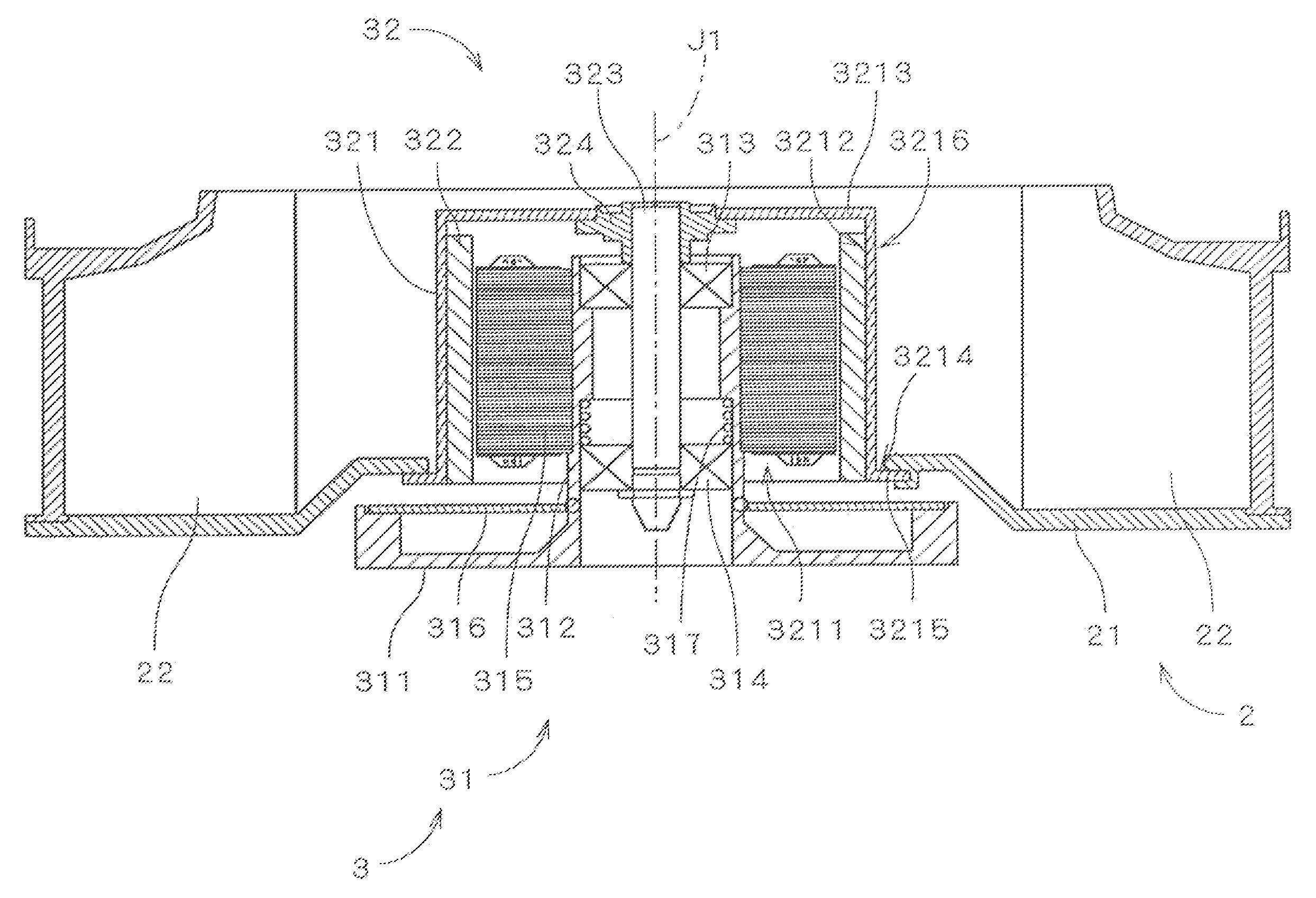
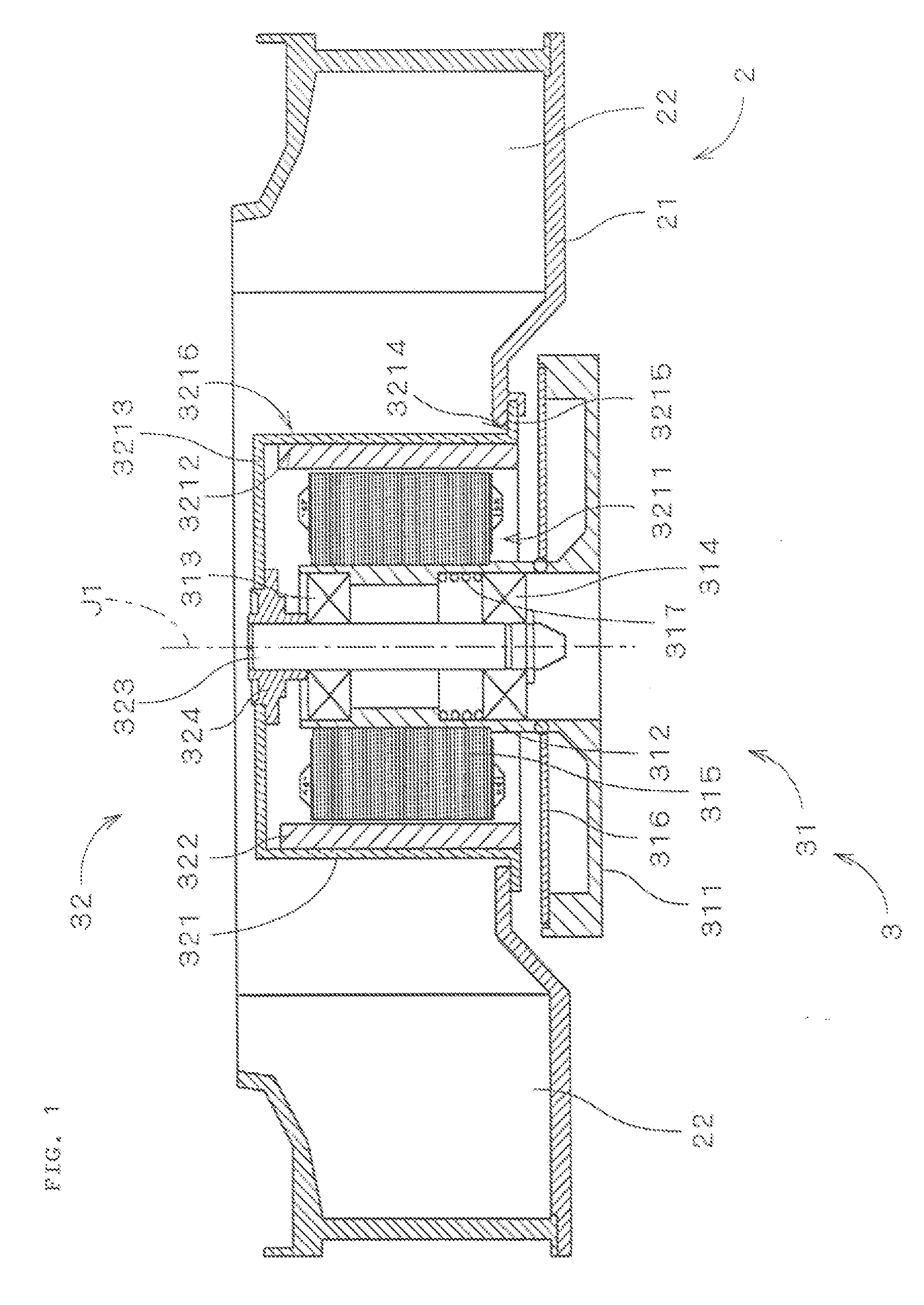
[0027]FIG. 1 is a vertical sectional view of a fan assembly 1 along a plane including a center axis J1, illustrating a configuration of the centrifugal type fan assembly 1 according to a first preferred embodiment of the present invention. As shown in FIG. 1, the fan assembly 1 includes an impeller portion 2 and a motor 3. The impeller portion 2 is attached to the motor 3 and generates air flow by rotation thereof. The motor 3 rotates impeller 2 about a center axis J1. The fan assembly 1 is accommodated within a housing (not shown) which defines a passage of air flow. In other words, the housing controls the air flow generated by the rotation of the impeller and sends the air outside of the housing. The fan assembly 1 is, for example, used as an air cooling fan for an electronic device.

[0028] The motor 3 is an outer rotor type motor, including a stator portion 31 which is a stationary assembly and a rotor portion 32 which is a rotary assembly. The rotor portion 32 is supported rota...


PUM


Abstract

A fan assembly includes an impeller portion generating an air flow and a motor that rotates the impeller portion about a center axis. The impeller portion is attached to a yoke of a rotor portion of the motor and is rotated with the yoke. A circular portion of the impeller is attached to a bottom opening of the yoke having a cylindrical shape whose top is covered by insert molding. Therefore, the impeller and the yoke may be securely fixed to each other. In addition, an outer side surface of the yoke is exposed to outside air such that the space arranged inward from the plurality of blades may be enlarged.

Description

BACKGROUND OF THE INVENTION [0001] 1. Field of the Invention [0002] The present invention generally relates to an electrically powered fan assembly used to blow air. [0003] 2. Description of the Related Art [0004] Conventionally, a centrifugal type fan assembly, taking air in an axial direction and exhausting the air in a radial direction, has the following configuration. Specifically, the conventional fan assembly includes an impeller having a plurality of blades arranged in a circumferential direction centered about a center axis, and a substantially cup-shaped portion arranged at the middle of the impeller into which a substantially cylindrical yoke made of magnetic material is press-fitted. In addition, a field magnet is attached to an inner side surface of the yoke. By virtue of this configuration, the impeller is rotatably supported around the center axis. The blades of the impeller are arranged on radially outer positions of the cup-shaped portion, and the cup-shaped portion ...

Claims


Application Information

Patent Timeline
Patent Type & Authority Applications(United States)
IPC IPC(8): F04B17/00
CPCF04D29/281F04D25/0613
Inventor NAGAMATSU, HIDEKIYAMAZAKI, SHOKIMORIYA, SHIGEYUKI
Owner NIDEC CORP
Why Eureka
Try Eureka