Ultrasound imaging beam-former apparatus and method

a beam-forming apparatus and ultrasound technology, applied in tomography, applications, instruments, etc., can solve the problems of high cost systems that may be so complex, require specialized technicians, and ultrasound is not practical for many routine tasks

Inactive Publication Date: 2007-01-18
UNIV OF VIRGINIA ALUMNI PATENTS FOUND
View PDF51 Cites 112 Cited by
  • Summary
  • Abstract
  • Description
  • Claims
  • Application Information

AI Technical Summary

Problems solved by technology

Medical imaging is a field dominated by high cost systems that may be so complex as to require specialized technicians for operation and the services of experienced medical doctors and nurses for image interpretation.
However it makes ultrasound impractical for many of the routine tasks for which it would be clinically useful.
While far less expensive than high-end systems, these systems are still very sophisticated and require a well-trained operator.
Furthermore, at this price few new applications may be opened.
Commercial ultrasound systems have been limited to one-dimensional (1-D) or linear transducer arrays until fairly recently.
Providing separate multiplex and receive circuitry is manageable with this many transducers, albeit with significant use of expensive high-voltage switches.
Maintaining separate receive, transmit, and multiplex partitioning for the transducers in such an array creates a tremendous burden in terms of cost, space, and complexity.
The power consumption and heat dissipation of thousands high-voltage multiplexers is enough to discourage the use of two-dimensional arrays in portable ultrasound imaging systems.
Implementation of time delays requires sufficient memory to hold a few hundred samples per channel to implement an adequate delay envelope, constraining system complexity.
Time delay beam-forming requires significant fast memory to implement a reasonable delay envelope.
Using a demodulation based approach to generate I / Q data may necessitate significant extra circuitry on each channel, while use of the Hilbert transform may require a significant amount of memory to hold the raw RF data.
Accordingly, existing ultrasound systems with thousands of separate transmit and receive switches may be too expensive for many applications.

Method used


Image

  • Ultrasound imaging beam-former apparatus and method
  • Ultrasound imaging beam-former apparatus and method
  • Ultrasound imaging beam-former apparatus and method

Examples


first embodiment

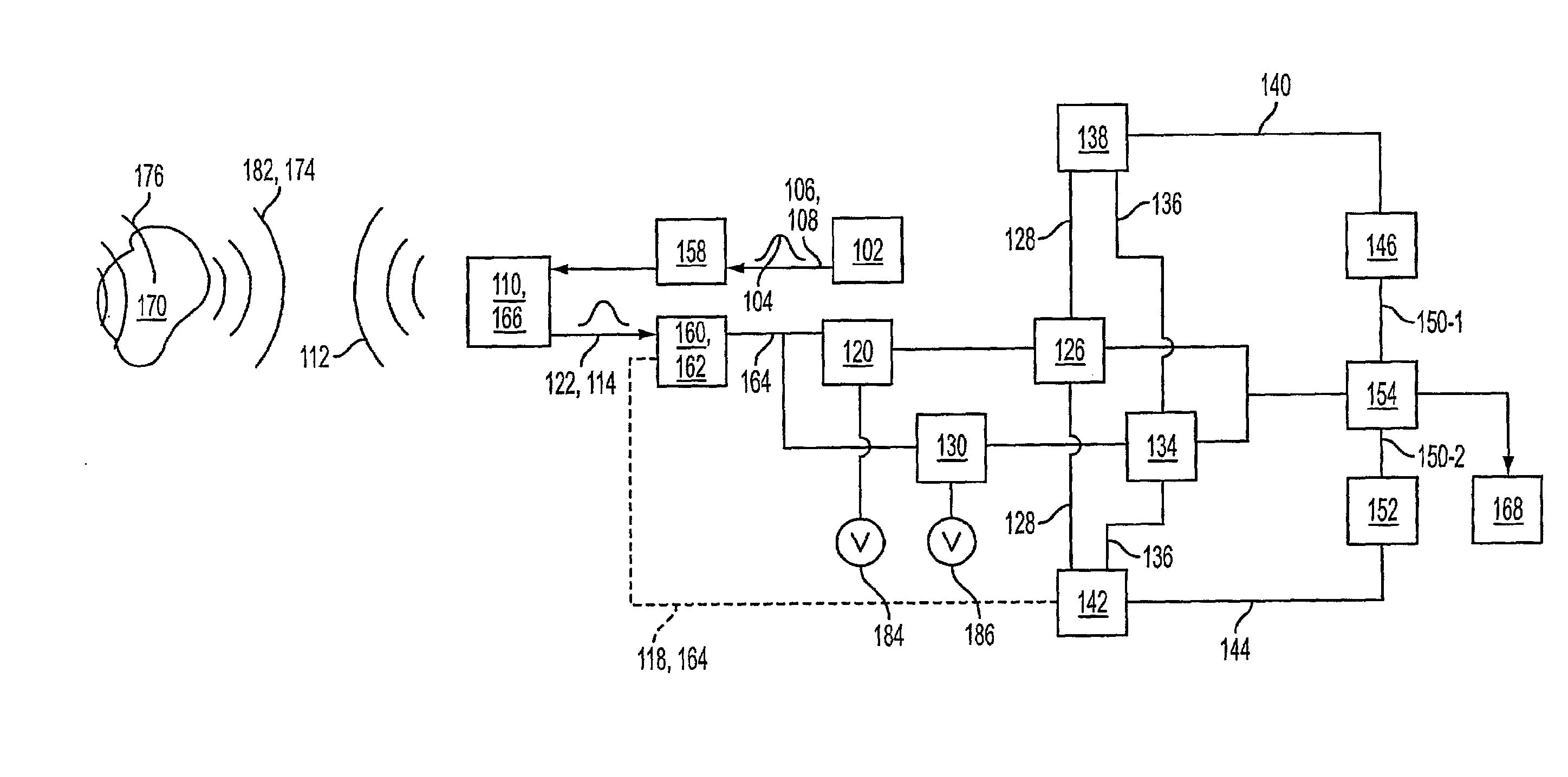
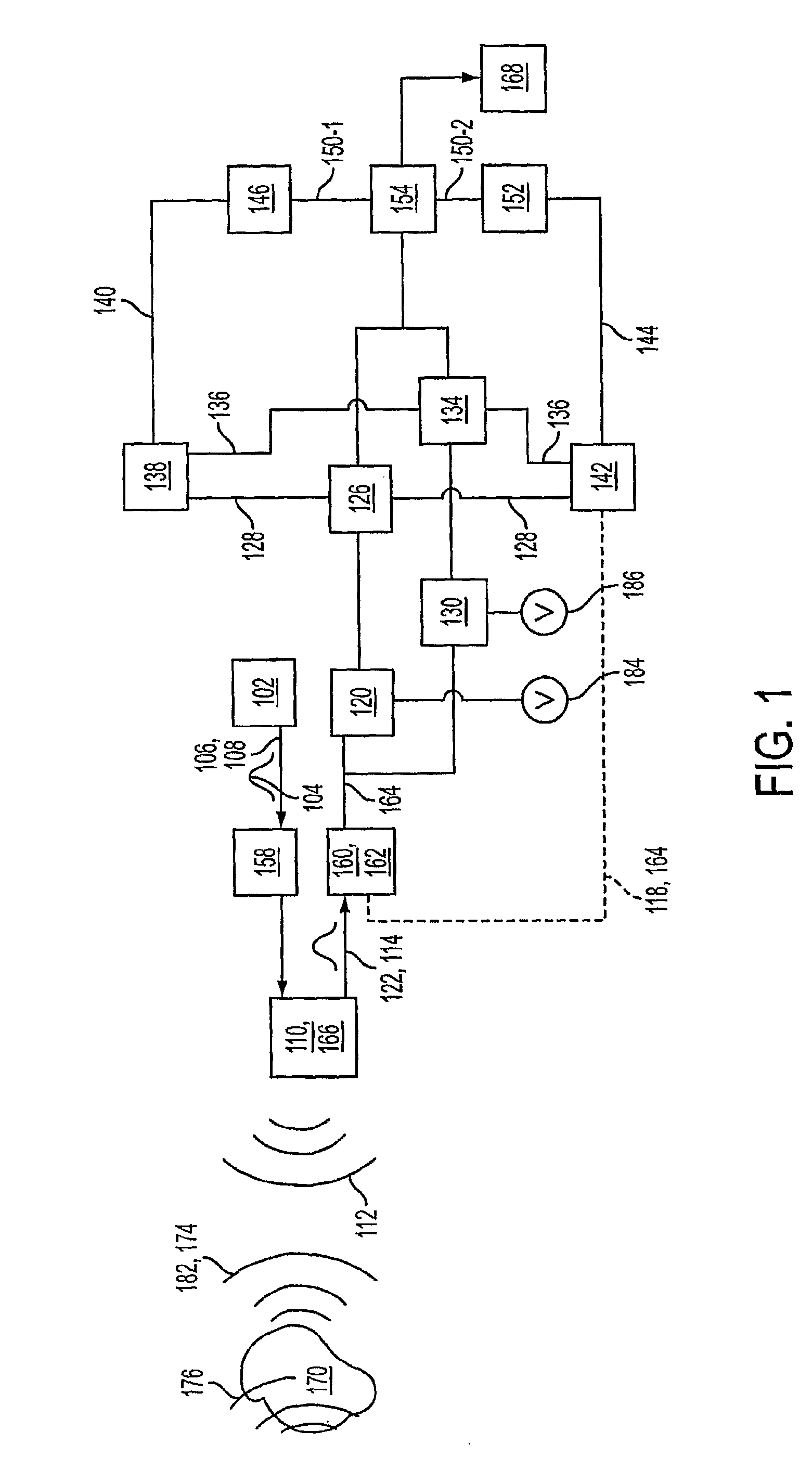
[0050] In FIG. 1 is shown an ultrasound imaging beam-former apparatus 100 according to the invention. Ultrasound imaging beam-former apparatus 100 may include a signal generator 102 for producing an outgoing signal 104 having an outgoing amplitude 106 at an outgoing time 108, as shown in FIG. 6A. In several embodiments, outgoing signal 104 may be an electrical signal, an electro-magnetic signal, or an optical signal.

[0051] If outgoing signal 104 is an optical signal, cross-talk between the circuits of ultrasound imaging beam-former apparatus 100 may be reduced or eliminated, since optical signals do not, in general, interfere with one another. This may allow ultrasound imaging beam-former apparatus 100 to be made smaller than an equivalent electronic device by increasing the density of the circuits. In one case, outgoing signal 104 may be processed as an optical signal and converted to an electrical signal to drive a transducer. An integrated circuit comprising ultrasound imaging be...

second embodiment

[0091] In the invention, shown in FIG. 4, apparatus 100 may include a second transducer 110-2 for converting outgoing signal 104 to second outgoing ultrasound 112-2. Some of second outgoing ultrasound 112-2 may return to second transducer 110-2 if it is reflected by object 170 as well. Second transducer 110-2 may convert at least a portion of outgoing ultrasound 112 and second outgoing ultrasound 112-2 to a second incoming signal 114-2 having a second period 116-2, as shown in FIG. 6C.

[0092] In one embodiment, signal receiver 118 may include a second in-phase sample-and-hold 120-2 connected receivably to second transducer 110-2 for sampling second incoming signal 114-2 at incoming time 122 and outputting a second in-phase amplitude 124-2 of second incoming signal 114-2 at substantially incoming time 122. In one embodiment, signal receiver 118 may include a second in-phase analog-to-digital converter 126-2 connected receivably to second in-phase sample-and-hold 120-2 for assigning a ...

third embodiment

[0095] In a third embodiment, a method of beam-forming for ultrasound imaging may include the steps of generating an outgoing signal 104 having an outgoing amplitude 106 at an outgoing time 108, transducing outgoing signal 104 to outgoing ultrasound 112, receiving at least a portion of reflected outgoing ultrasound 112, transducing reflected ultrasound to an incoming signal 114 having a period 116, sampling incoming signal 114 at an incoming time 122 to produce an in-phase amplitude 124 of incoming signal 114, assigning an in-phase digital value 128 to in-phase amplitude 124 sampling incoming signal 114 at substantially one-quarter of period 116 after incoming time 122 to produce a quadrature amplitude 132 of incoming signal 114, assigning a quadrature digital value 136 to quadrature amplitude 132, calculating a magnitude 140 at incoming time 122 based on in-phase digital value 128 and quadrature digital value 136, calculating a phase 144 at incoming time 122 based on in-phase digit...


PUM


Abstract

In some illustrative embodiments, an incoming signal from a transducer in an ultrasound imaging beam-former apparatus is applied to an in-phase sample-and-hold and a quadrature sample-and-hold. The quadrature sample-and-hold may be clocked a quarter period behind the in-phase sample-and-hold. The output of the sample-and-holds are applied to in-phase and quadrature analog-to-digital converters. A magnitude calculator receives the in-phase and quadrature digital values, and outputs a magnitude. A phase calculator receives the in-phase and quadrature digital values, and outputs a phase. An apodizer applies a difference between an amplitude of the outgoing signal and the magnitude and applies a first illumination to a image point in substantial proportion to the difference, and a phase rotator applies a second illumination to the image point in substantial proportion to the phase.

Description

CROSS-REFERENCE TO RELATED APPLICATIONS [0001] The present application is National Stage filing under 35 U.S.C. 371 of International Applications No. PCT / US2004 / 000887 which claims priority to U.S. Provisional Application Ser. Nos. 60 / 440,020 filed on Jan. 14, 2003, 60 / 439,990 filed on Jan. 14, 2003, and 60 / 440,262 filed on Jan. 15, 2003 the entire disclosures of which are incorporated herein by reference.BACKGROUND [0002] 1. Field of the Invention [0003] The present invention relates to ultrasonic diagnostic imaging systems and methods. More specifically, the preferred embodiments relate to a device and method for ultrasound imaging beam-forming that may be incorporated in a substantially integrated hand-held ultrasonic diagnostic imaging instrument. [0004] 2. Introduction [0005] Medical imaging is a field dominated by high cost systems that may be so complex as to require specialized technicians for operation and the services of experienced medical doctors and nurses for image int...

Claims


Application Information

Patent Timeline
Patent Type & Authority Applications(United States)
IPC IPC(8): A61B8/00A61BA61B8/14G01S15/89G10K11/34
CPCA61B8/00G01S7/52028G01S7/52034G01S15/8915G01S15/8959G01S15/8995G10K11/346G01S7/5208A61B8/4483A61B8/145A61B8/4488A61B8/4494A61B8/461A61B8/5207G01S7/52085
Inventor BLALOCK, TRAVIS N.WALKER, WILLIAM F.HOSSACK, JOHN A.
Owner UNIV OF VIRGINIA ALUMNI PATENTS FOUND
Why Eureka
Try Eureka