Ultrasonic transducer drive

a transducer and ultrasonic technology, applied in the field of ultrasonic diagnostic imaging systems and methods, can solve the problems of high cost systems that may be so complex, require specialized technicians, and ultrasound is not practical for many of the routine tasks,

Active Publication Date: 2007-01-18
UNIV OF VIRGINIA ALUMNI PATENTS FOUND
View PDF46 Cites 80 Cited by
  • Summary
  • Abstract
  • Description
  • Claims
  • Application Information

AI Technical Summary

Benefits of technology

[0038] The preferred embodiments of the present invention may improve significantly upon existing methods and/or apparatuses. In particular, the present invention comprises an ultrasonic transd

Problems solved by technology

Medical imaging is a field dominated by high cost systems that may be so complex as to require specialized technicians for operation and the services of experienced medical doctors and nurses for image interpretation.
However it makes ultrasound impractical for many of the routine tasks for which it would be clinically useful.
While far less expensive than high-end systems, these systems are still very sophisticated and require a well-trained operator.
Furthermore, at this price few new applications may be opened.
Conventional system configurations can be awkward to use because of the lengthy cable involved.
Finally, the typical large size of the beamformer limits the system's portability.
This conventional TX/RX switch 104 is the sou

Method used


Image

  • Ultrasonic transducer drive
  • Ultrasonic transducer drive
  • Ultrasonic transducer drive

Examples


first embodiment

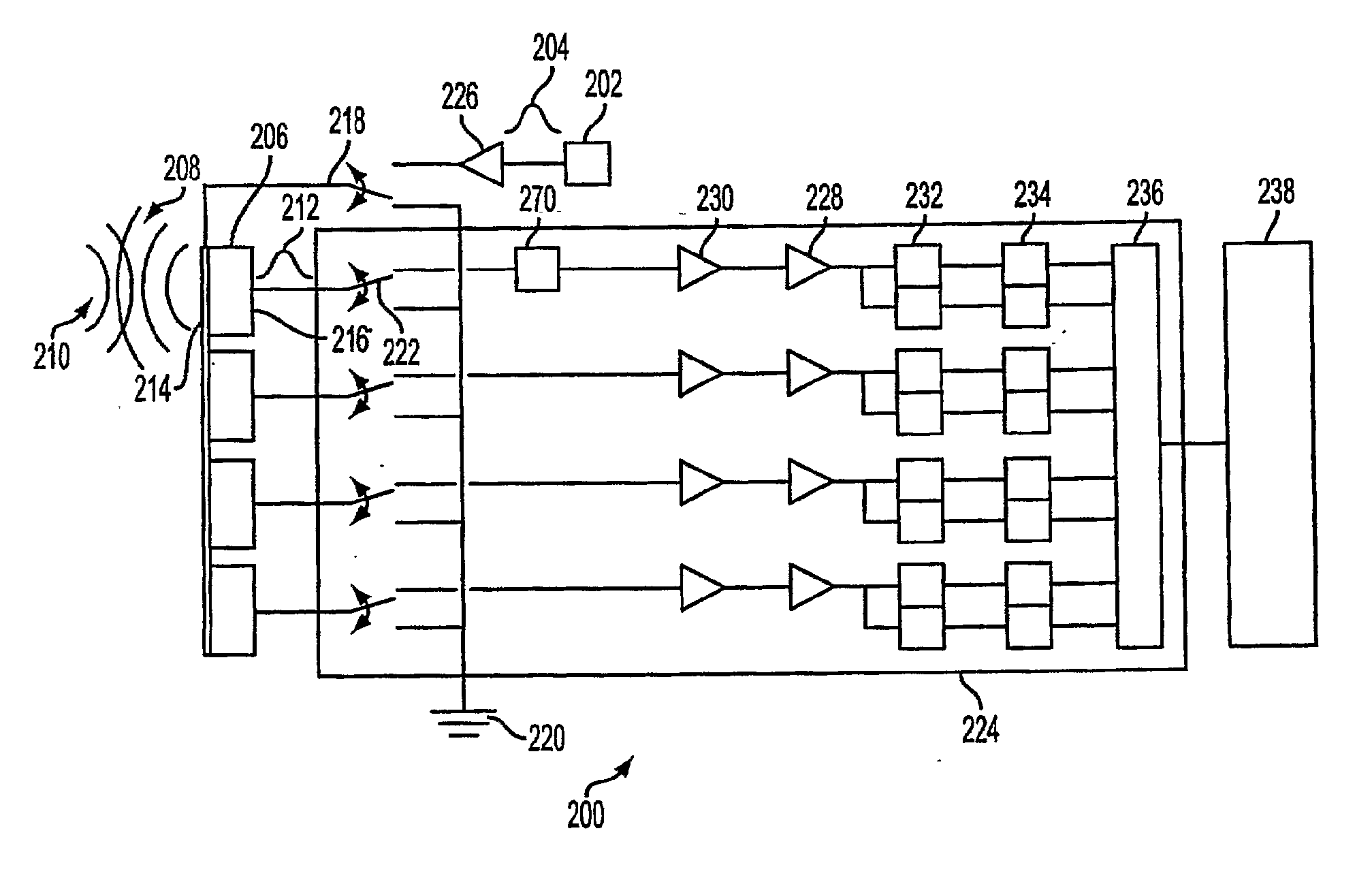
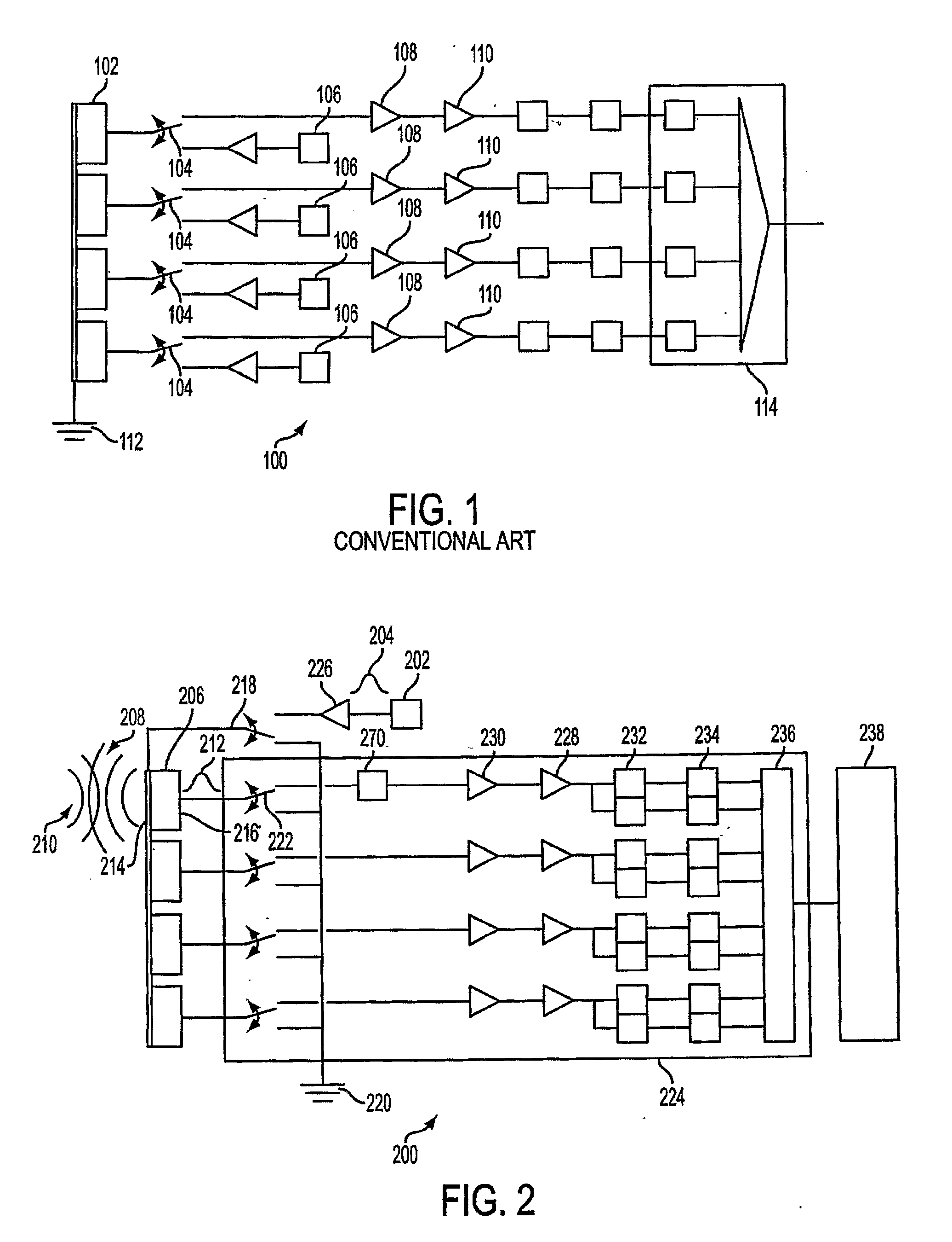
[0051] In FIG. 2 is shown an ultrasonic transducer drive 200 according to the invention. Ultrasonic transducer drive 200 may be used in a relatively small, inexpensive, and portable ultrasound imaging system 300 such as that shown in FIG. 6. Ultrasonic transducer drive 200 may include a signal generator 202 for producing an outgoing signal 204. In several embodiments, outgoing signal 204 may be an electrical signal, an electromagnetic signal, or an optical signal.

[0052] If outgoing signal 204 is an optical signal, cross-talk between the circuits of ultrasonic transducer drive 200 may be reduced or eliminated, since optical signals do not, in general, interfere with one another. This may allow ultrasonic transducer drive 200 to be made smaller than an equivalent electronic device by increasing the density of the circuits. in one case, outgoing signal 204 may be processed as an optical signal and converted to an electrical signal to drive a transducer. An integrated circuit comprising...

second embodiment

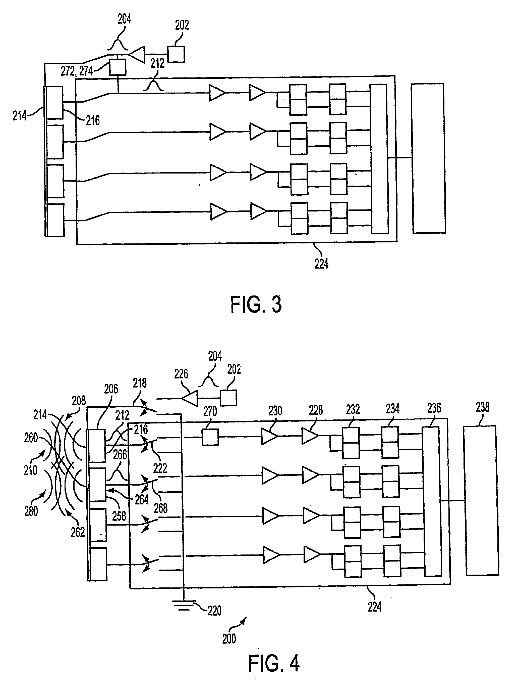
[0069] In a second embodiment, shown in FIG. 3, signal receiver 224 may receive incoming signal 212 while signal generator 202 is generating outgoing signal 204, in the manner of a full-duplex transceiver. In this embodiment, transmit switch 218 and receive switch 222 may be dispensed with, and outgoing signal 204 may be coupled to transmit side 214 while signal receiver 224 is coupled to receive side 216. In this embodiment, an echo canceller 272 may be inserted between outgoing signal 204 and incoming signal 212 to isolate incoming signal 212 from outgoing signal 204. Echo canceller 272 may be an equalizer, such as an adaptive equalizer. A voltage regulator 274, such as a diode running in reverse breakdown mode, may also isolate pre-amplifier 230 or receiver amplifier 228 from the high. voltage levels of outgoing signal 204.

[0070] In a second embodiment, shown in FIG. 3, ultrasonic transducer drive 200 may also include a second transducer 258 having a second transmit side 260 for ...

third embodiment

[0071] In a third embodiment, shown in FIG. 4, ultrasonic transducer drive 200 may include an array of transducers 258-1 -258-n, each having a transmit side 260-1 -260-n for converting outgoing signal 204 to outgoing ultrasound 208 and a receive side 264-1-264-n for converting at least a portion of reflected ultrasound 210 to incoming signals 266-1-266-n. In this embodiment, each transmit side 260-1-260-n may be connected operably to transmit switch 218 so transmit switch 218 can connect all of transmit sides 260-1-260-n switchably to signal generator 202 for substantially first predetermined period of time and connect all of transmit sides 260-1-260-n to reference potential 220 for substantially second predetermined period of time. In this embodiment, each receive side 264-1-264-n may be connected operably to a separate receive switch 268-1-268-n so each receive switch 268-1-268-n can connect each receive side 264-1-264-n switchably to signal receiver 224 for substantially second p...


PUM


Abstract

In some illustrative embodiments, an ultrasonic transducer drive includes a signal generator for producing an outgoing signal and a transducer for converting the outgoing signal to outgoing ultrasound. The transducer may also convert at least a portion of ultrasound reflected by an object to an incoming signal. The transducer may have a transmit side connected conductably to the signal generator during at least a first predetermined period of time and a receive side connected conductably to a signal receiver during at least a second predetermined period of time. A shunt may be connectable between the receive side and a reference potential. The signal generator may generate the outgoing signal during at least substantially the first predetermined period of time while the shunt connects the receive side to the reference potential. The signal receiver may receive the incoming signal during substantially the second predetermined period of time while the shunt is substantially open.

Description

Cross-reference to Related Applications [0001] The present application is National Stage filing under 35 U.S.C. 371 of International Applications No. PCT / US2004 / 000888 which claims priority to United States Provisional Application Ser. Nos. 60 / 440,020 filed on Jan. 14, 2003, 60 / 439,990 filed on Jan. 14, 2003, and 60 / 440,262 filed on Jan. 15, 2003 the entire disclosures of which are incorporated herein by reference.BACKGROUND [0002] 1. Field of the Invention [0003] The present invention relates to ultrasonic diagnostic imaging systems and methods. More specifically, the preferred embodiments relate to a device and method for driving an ultrasound transducer that may be incorporated in a substantially integrated hand held ultrasonic diagnostic imaging instrument. [0004] 2. Introduction [0005] Medical imaging is a field dominated by high cost systems that may be so complex as to require specialized technicians for operation and the services of experienced medical doctors and nurses for...

Claims


Application Information

Patent Timeline
IPC IPC(8): A61B8/00
CPCG01S7/5208G01S7/52017A61B8/4427A61B8/4483
Inventor BLALOCK, TRAVIS N.WALKER, WILLIAM F.HOSSACK, JOHN A.
Owner UNIV OF VIRGINIA ALUMNI PATENTS FOUND
Why Eureka
Try Eureka