Audio coding

a technology of audio coding and coding methods, applied in the field of audio coding, can solve the problems of reducing the degree of coding, affecting the quality of coding, so as to achieve the effect of fewer audible artifacts

Active Publication Date: 2007-01-18
FRAUNHOFER GESELLSCHAFT ZUR FOERDERUNG DER ANGEWANDTEN FORSCHUNG EV
View PDF6 Cites 37 Cited by
  • Summary
  • Abstract
  • Description
  • Claims
  • Application Information

AI Technical Summary

Benefits of technology

[0013] It is an object of the present invention to provide an audi

Problems solved by technology

Audio compression methods, such as, for example, the MP3 format, experience a limit in their applicability when audio data is to be transferred via a bit rate-limited transmission channel in a, on the one hand, compressed manner, but, on the other hand, with as small a delay time as possible.
The quantizing noise caused by this is white noise.
Although the audio coding scheme described in the article mentioned above already reduces the delay time for many applications to a sufficient degree, a problem in the above scheme is that, due to the requirement of having to transfer the masking threshold or transfer function of the coder-side filter, subsequently referred to as pre-filter, the transfer channel is loaded to a relatively high degree even though the filter coefficients will only be transferred when a predetermined threshold is exceeded.
Another disadvantage of the above coding scheme is that, due to the fact that the masking threshold or inverse thereof has to be made available on the decoder side by the parameter set x# to be transferred, a compromise has to be made between the lowest possible bit rate or high compression ratio on the one hand and the most precise approximation possible or parameterization of the masking threshold or inverse thereof on the other hand.
Thus, it is inevitable for the quantizing noise adjusted t

Method used


Image

  • Audio coding
  • Audio coding
  • Audio coding

Examples


Embodiment Construction

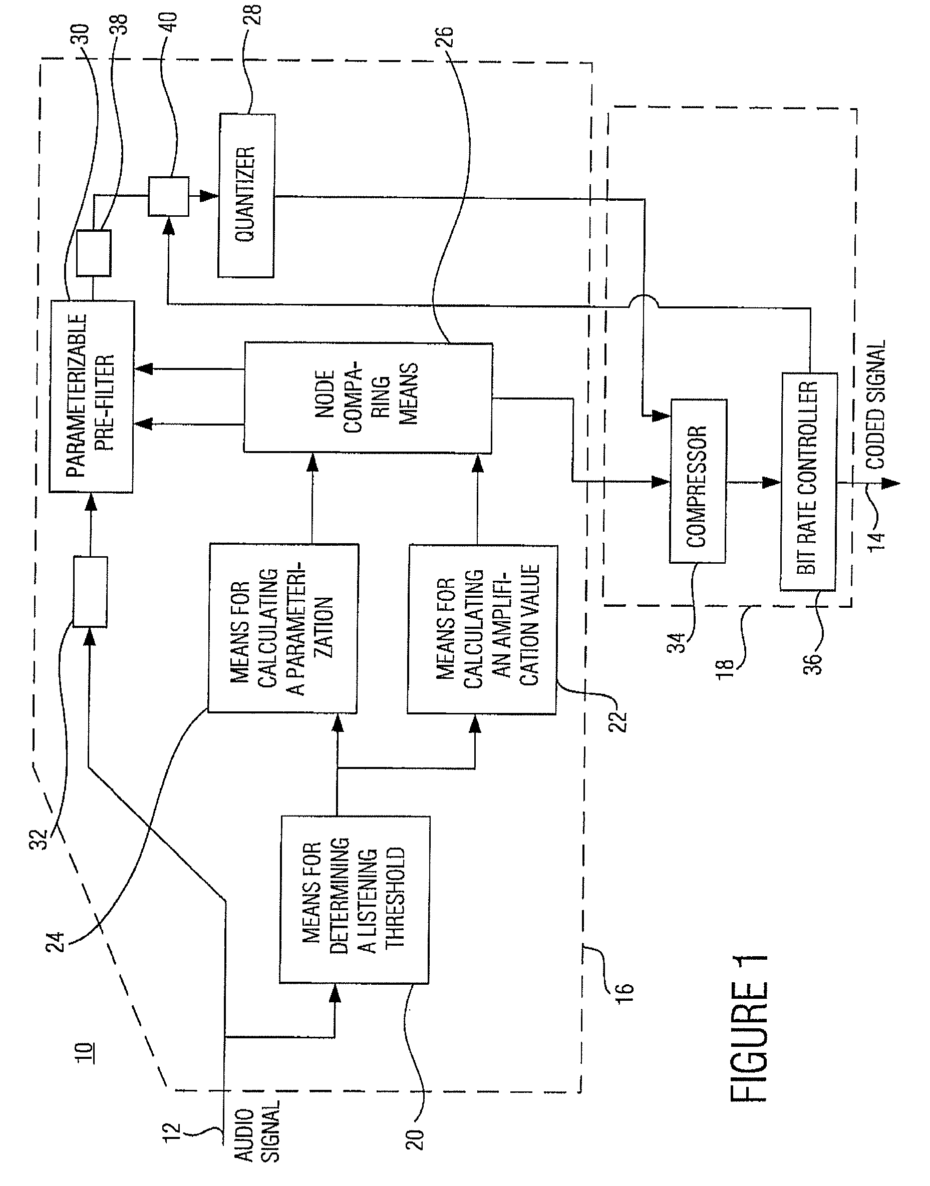
[0037]FIG. 1 shows an audio coder according to an embodiment of the present invention. The audio coder, which is generally indicated by 10, includes a data input 12 where it receives the audio signal to be coded, which, as will be explained in greater detail later referring to FIG. 5a, consists of a sequence of audio values or sample values, and a data output where the coded signal is output, the information content of which will be discussed in greater detail referring to FIG. 5b.

[0038] The audio coder 10 of FIG. 1 is divided into an irrelevance reduction part 16 and a redundancy reduction part 18. The irrelevance reduction part 16 includes means 20 for determining a listening threshold, means 22 for calculating an amplification value, means 24 for calculating a parameterization, node comparing means 26, a quantizer 28 and a parameterizable pre-filter 30 and an input FIFO (first in first out) buffer 32, a buffer or memory 38 and a multiplier or multiplying means 40. The redundancy...


PUM


Abstract

The central idea of the present invention is that the prior procedure, namely interpolation relative to the filter coefficients and the amplification value, for obtaining interpolated values for the intermediate audio values starting from the nodes has to be dismissed. Coding containing less audible artifacts can be obtained by not interpolating the amplification value, but rather taking the power limit derived from the masking threshold, preferably as the area below the square of the magnitude of the masking threshold, for each node, i.e. for each parameterization to be transferred, and then performing the interpolation between these power limits of neighboring nodes, such as, for example, a linear interpolation. On both the coder and the decoder side, an amplification value can then be calculated from the intermediate power limit determined such that the quantizing noise caused by quantization, which has a constant frequency before post-filtering on the decoder side, is below the power limit or corresponds thereto after post-filtering.

Description

CROSS-REFERENCE TO RELATED APPLICATION [0001] This application is a continuation of copending International Application No. PCT / EP2005 / 001350, filed Feb. 10, 2005, which designated the United States and was not published in English, and is incorporated herein by reference in its entirety, and which claimed priority to German Patent Application No. 102004007200.0, filed on Feb. 13, 2004.BACKGROUND OF THE INVENTION [0002] 1. Field of the Invention [0003] The present invention relates to audio coding in general and, in particular, to audio coding allowing audio signals to be coded with a short delay time. [0004] 2. Description of the Related Art [0005] The audio compression method best known at present is MPEG-1 Layer III. With this compression method, the sample or audio values of an audio signal are coded into a coded signal in a lossy manner. Put differently, irrelevance and redundancy of the original audio signal are reduced or ideally removed when compressing. In order to achieve ...

Claims


Application Information

Patent Timeline
IPC IPC(8): G10L19/00G10L19/032G10L19/26
CPCG10L19/265G10L19/032G10L19/00H03M7/30G11B20/10
Inventor SCHULLER, GERALDWABNIK, STEFANGAYER, MARC
Owner FRAUNHOFER GESELLSCHAFT ZUR FOERDERUNG DER ANGEWANDTEN FORSCHUNG EV
Why Eureka
Try Eureka