
Device for fixing scraper strips to a printing roller scraper

a technology of printing scraper and scraper, which is applied in the direction of printing presses, rotary presses, printing, etc., can solve the problems of requiring a compressed air installation, requiring a complicated and expensive system, and a relative long time for mounting and dismounting of scraper strips, etc., and achieves simple application, fast and simple construction.

Inactive Publication Date: 2007-01-25
COMEXI GRP IND
View PDF11 Cites 8 Cited by
  • Summary
  • Abstract
  • Description
  • Claims
  • Application Information

AI Technical Summary

Benefits of technology

[0004] The purpose of the present invention is to solve or mitigate the previously described inconveniences by providing a device for securing doctor blades to a printing roller doctor assembly that includes releasable securing means to join at least one doctor blade to the body of the doctor assembly, where said releasable securing means are of simple construction and fast, simple application without any need for tools.
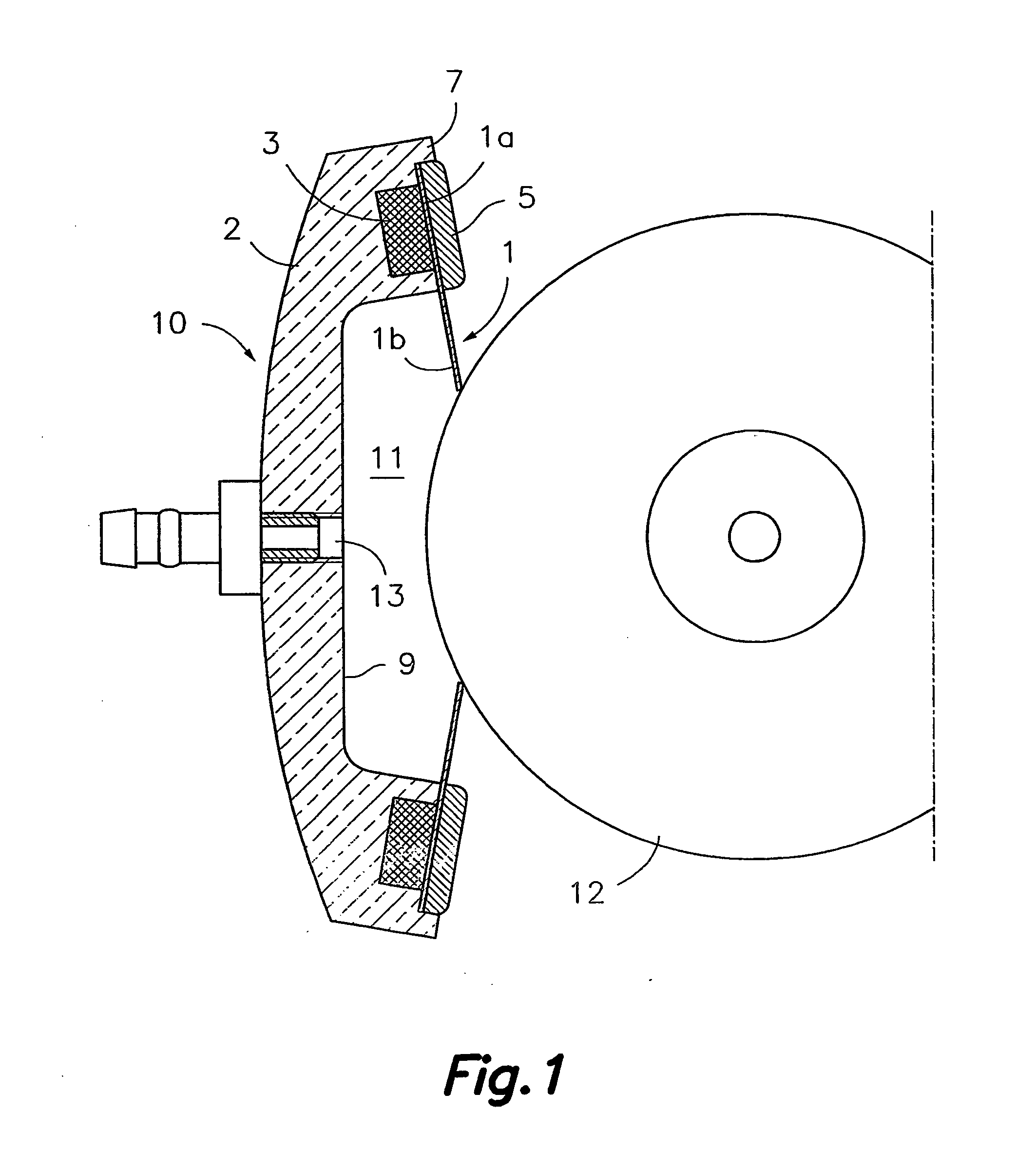
[0008] With the inclusion of one or more magnetic elements in accordance with this invention, releasable securing means are provided for joining the doctor blade to the body of the doctor assembly, and which are of simple and economic construction and easy and simple to handle without any need for tools or the installation of expensive power supplies.

Problems solved by technology

The securing of the blades to the doctor body has been being achieved by means of releasable securing elements, such as screws, which have the inconvenience of comprising a large number of loose items that require specific tools and a relatively long time for its mounting and dismounting.
One inconvenience of this system is that it requires a double mechanism; a first mechanism to press the clamp against the body and a second mechanism to counteract said pressure.
Because of this, the system is both complicated and expensive.
Moreover, in certain embodiments, the cited movement mechanism is driven by compressed air, which involves the additional inconvenience of requiring a compressed air installation.

Method used


Image

  • Device for fixing scraper strips to a printing roller scraper
  • Device for fixing scraper strips to a printing roller scraper
  • Device for fixing scraper strips to a printing roller scraper

Examples


Embodiment Construction

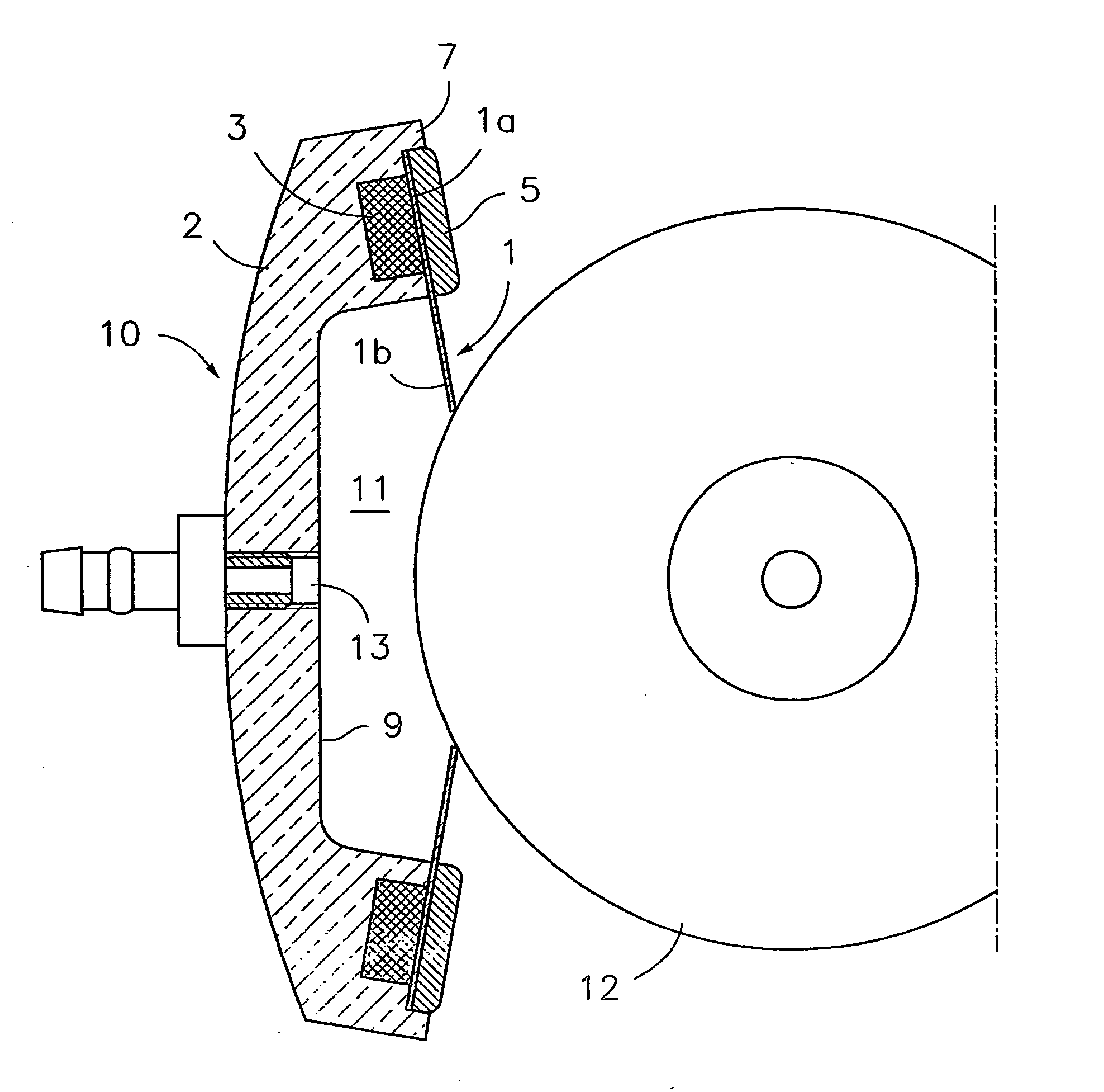
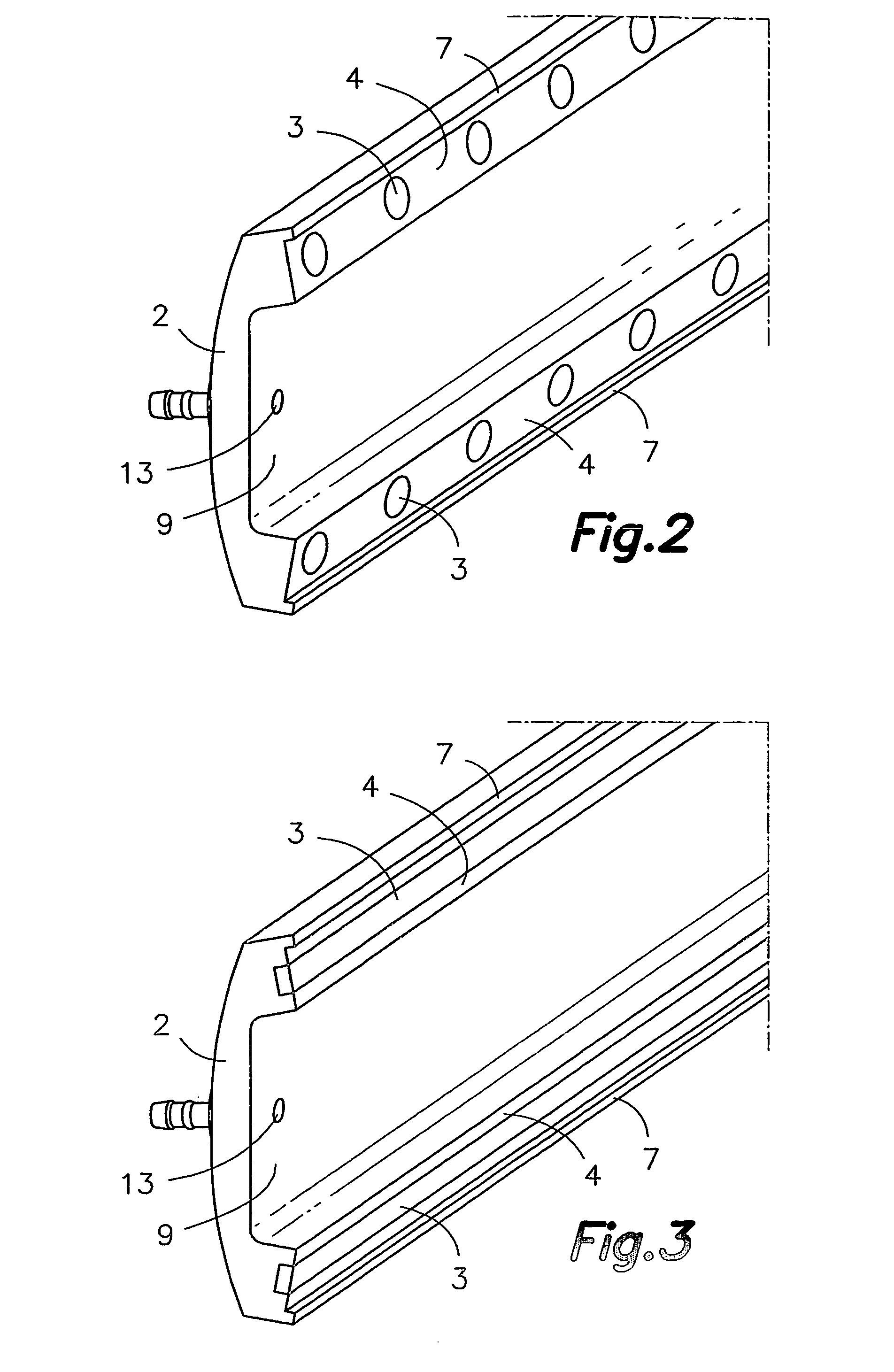
[0015] First referring to FIG. 1, there is shown a doctor assembly 10 for a printing roller 12 of a well-known type of flexographic printer. The mentioned doctor assembly 10 comprises an elongated body 2 that has a longitudinal groove 9 facing the printing roller 12 and two supporting surfaces 4 (see FIGS. 2 and 3) located on both sides of the mentioned groove 9. The cited supporting surfaces 4 are designed for the installation of a pair of doctor blades 1 arranged to make contact with the outer surface of the roller 12. Releasable securing means allow at least one longitudinal supporting portion la of each doctor blade 1 to be joined to the body 2 of the doctor assembly 10 so that another free longitudinal portion 1b of said doctor blade 1 is cantilevered. The free ends of said cantilevered portions 1b make elastic contact with the surface of the roller 12. The longitudinal groove 9 is suitably closed at its lateral ends so that, when in use, a closed chamber 11 is formed between t...


PUM


Abstract

The invention relates to a device for fixing scraper strips to a printing roller scraper. The inventive device comprises at least one magnetic element (3) which is configured and disposed such as to hold a first face of a longitudinal support portion (1a) of at least one scraper strip (1) in firm contact with a support surface of a body (2) of said scraper (10), a second free longitudinal portion (1b) of said scraper strip (1) occupying a projecting position. Alternatively, the magnetic element (3) is also configured and disposed such as to maintain a hold-down plate (5) in firm contact with a second face of the support portion (1a) of the scraper strip (1), whereby said second face is located opposite the aforementioned first face which is in contact with the body (2). In this way, the support portion (1a) of the scraper strip (1) is trapped between the hold-down plate (5) and the support surface of the body (2).

Description

SCOPE OF THE INVENTION [0001] This invention concerns to a device for securing doctor blades to a printing roller doctor assembly, applicable to flexographic printers, for example. TECHNICAL BACKGROUND [0002] In many applications in which rollers are used in contact with more or less sticky substances, doctor devices are employed to clean or control the presence of said substance on the roller surface. Usually this doctor takes the form of a blade secured to an elongated body generally located in parallel to a printing roller. This blade has at least one longitudinal supporting portion joined to a supporting surface of said body and another free longitudinal portion that projects outwards cantilevered, the end of which is in contact with the roller. A doctor device is known, for example, in flexographic printers, in which said elongated body has a longitudinal groove facing the printing roller and two of said supporting surfaces located at both sides of the mentioned groove and desi...

Claims


Application Information

Patent Timeline
Patent Type & Authority Applications(United States)
IPC IPC(8): B41F31/00B41F9/10
CPCB41F31/027B41F9/1036
Inventor DAVILA CASITAS, JOANVINAS TURRO, MIQUELPUIG I VILA, JORDI
Owner COMEXI GRP IND
Learn More