Intake manifold with low chatter shaft system

a technology of low chatter and shaft, which is applied in the direction of charge feed system, combustion air/fuel air treatment, machine/engine, etc., can solve the problems of shaft misalignment, shaft durability and strength decline, and other assembly components, etc., to achieve low friction, dampen vibration, and reduce friction

Active Publication Date: 2007-01-25
SIEMENS VDO AUTOMOTIVE INC
View PDF15 Cites 3 Cited by
  • Summary
  • Abstract
  • Description
  • Claims
  • Application Information

AI Technical Summary

Benefits of technology

[0007] The shaft assembly may be a shaft manufactured from metal. Bearings located at each end provide hard mounting surfaces for the shaft assembly when assembled with the housing. The bearings support the shaft within the housing and allow the shaft to freely rotate. Load is applied on the bearings to hold the shaft assembly rigid within the housing. The bearings are low friction and assist in correcting any non-circular rotation of the shaft that may results from imperfect manufacturing. Supports on the intake insert at least partially surround the bearings once assembled and apply load to the bearings to retain the shaft within the housing.
[0008] Bushings are spaced along the shaft. The bushings are preferably two-part bushings with rubber seals and plastic sleeves. The rubber seals absorb vibrations and the plastic sleeves assist is providing a low friction surface for shaft assembly rotation. Journal pockets in the housing and in the intake insert surround the bushings. Isolators located within the journal pockets surround the bushings and assist in dampening vibrations.

Problems solved by technology

However, plastic shafts have lower durability and strength.
During manufacture, imperfections may occur in the shaft, other assembly components, and the manifold housing due to manufacturing tolerances.
The imperfections in the shaft assembly and manifold housing may lead to misalignment of the shaft when assembled into the intake manifold housing.
However, during operation of the vehicle the misalignment of the shaft assembly may cause non-circular rotation of the shaft assembly.
The non-circular rotation creates noise.
In addition, imperfect fit between the shaft and manifold housing causes the shaft to vibrate against the manifold housing during engine operation.
The vibrations also create chatter noise.

Method used


Image

  • Intake manifold with low chatter shaft system
  • Intake manifold with low chatter shaft system
  • Intake manifold with low chatter shaft system

Examples


Embodiment Construction

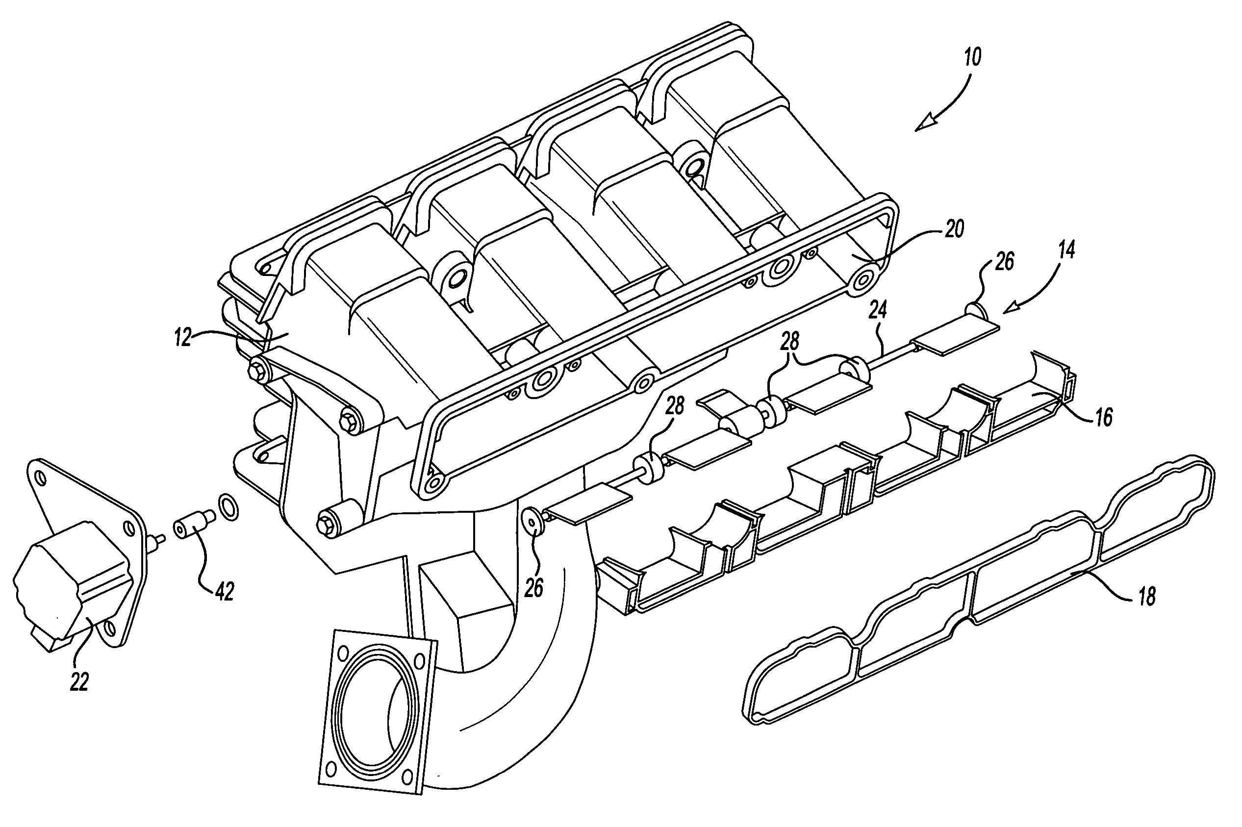
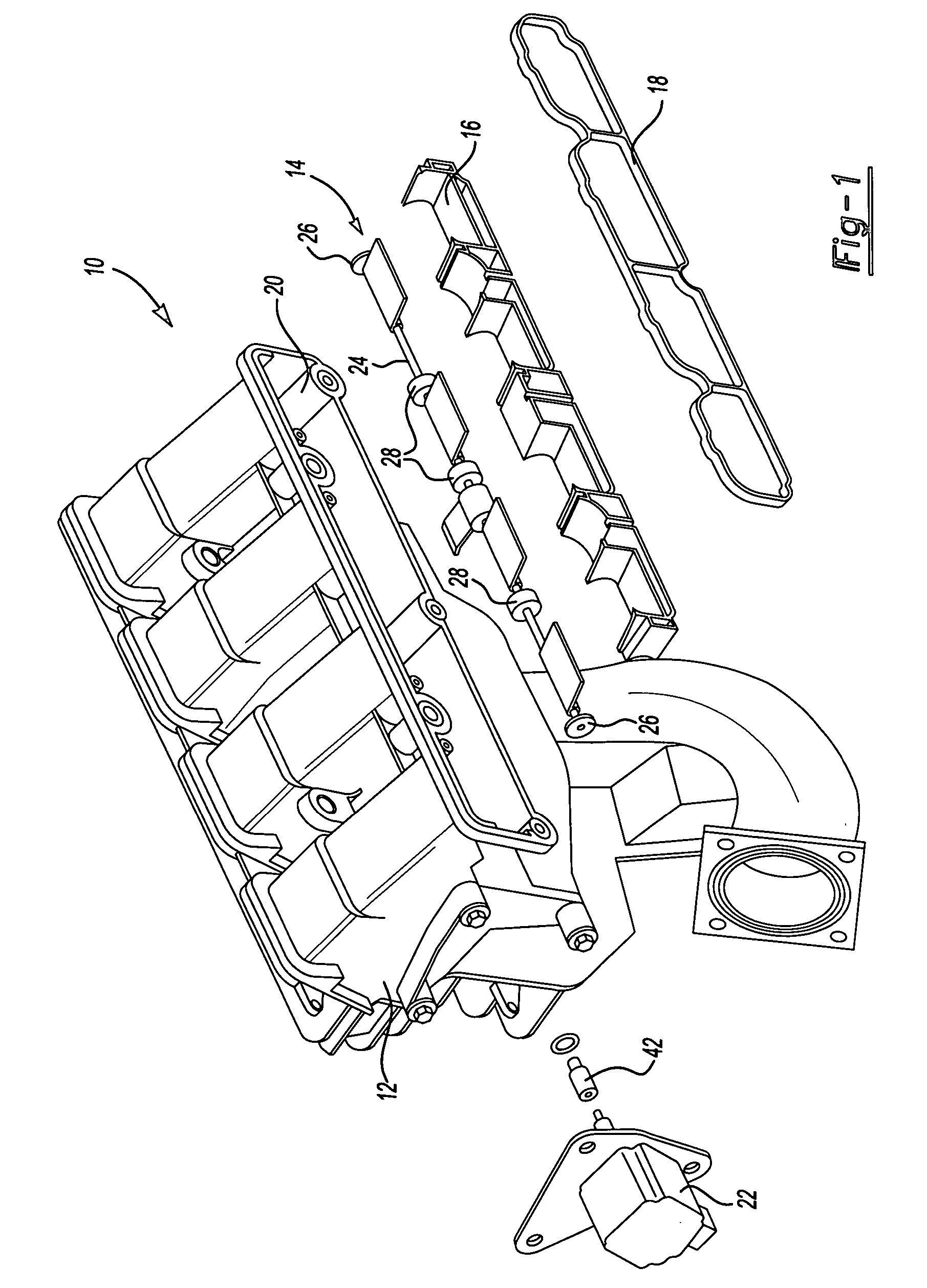
[0015]FIG. 1 shows an intake manifold assembly 10. The intake manifold assembly 10 includes a housing 12, a shaft assembly 14, an intake insert 16, and a flange seal 18. The shaft assembly 14 is assembled into opening 20 within the housing 12. The intake insert 16 is placed within the opening 20 to retain and support the shaft assembly 14. The flange seal 18 is assembled last. The flange seal 18 seals around the opening 20 once the intake manifold assembly 10 is mounted to the engine. Bolts or other fasteners may be used to retain the shaft assembly 14 within the housing 12 until the intake manifold assembly 10 can be mounted to the engine. Once mounted to the engine, the shaft assembly 14 is held in place by the engine. An actuator 22 is mounted on the housing 12. Following assembly, actuator 22 is connected to the shaft assembly 14. During operation of the engine, the actuator 22 controls airflow through the main passage of the intake manifold assembly 10 by rotating the shaft ass...


PUM


Abstract

An intake manifold assembly includes a housing, a shaft assembly, and an intake insert. The shaft assembly has a metal shaft with bearings located at each end to provide hard mounting surfaces for the shaft assembly when assembled in the housing. The bearings support the shaft within the housing and allow the shaft to freely rotate. Bushings are spaced along the shaft to absorb vibrations and assist is providing a low friction surface for shaft assembly rotation. Journal pockets in the housing and in the intake insert surround the bushings. Isolators located within the journal pockets and housing surround the bushings and assist in dampening vibrations.

Description

BACKGROUND OF THE INVENTION [0001] The invention is an arrangement for a shaft assembly in an intake manifold housing which reduces noise and vibration of the shaft and assembly components. [0002] Intake manifolds control the amount of air entering internal combustion engines. Air enters the intake manifold and flows through to the engine. Intake manifolds use shaft and blade assemblies to control the intake of air into the manifold assembly and through to the engine. [0003] The shafts have commonly been manufactured from plastic and coated with rubber to lower vibration and noise. However, plastic shafts have lower durability and strength. During manufacture, imperfections may occur in the shaft, other assembly components, and the manifold housing due to manufacturing tolerances. The imperfections in the shaft assembly and manifold housing may lead to misalignment of the shaft when assembled into the intake manifold housing. The imperfections may be minimal while at rest. However, ...

Claims


Application Information

Patent Timeline
Patent Type & Authority Applications(United States)
IPC IPC(8): F02M35/10
CPCF02D9/103F02D9/106F02M35/112F02M35/10085F02D9/1095
Inventor LETOURNEAU, MARKMAMMARELLA, JOHN
Owner SIEMENS VDO AUTOMOTIVE INC
Why Eureka
Try Eureka