Tubular running apparatus

Inactive Publication Date: 2007-01-25
WEATHERFORDLAMB
View PDF10 Cites 35 Cited by
  • Summary
  • Abstract
  • Description
  • Claims
  • Application Information

AI Technical Summary

Benefits of technology

[0014] In another embodiment, a method for preventing a collision between a first and a second component at a well comprises sensing the location of the first component relative to the second component; tra

Problems solved by technology

The distance between an operator and the aligning/stabbing makes it difficult for the operator to judge the location of drilling tools in relation to other drilling tools.
The operator's view of the drilling tools is further obstructed by the drilling tools relative to each other or impaired by adverse weather and poor lighting.
These factors sometimes cause an operator to make a mistake thereby

Method used


Image

  • Tubular running apparatus
  • Tubular running apparatus
  • Tubular running apparatus

Examples


Example

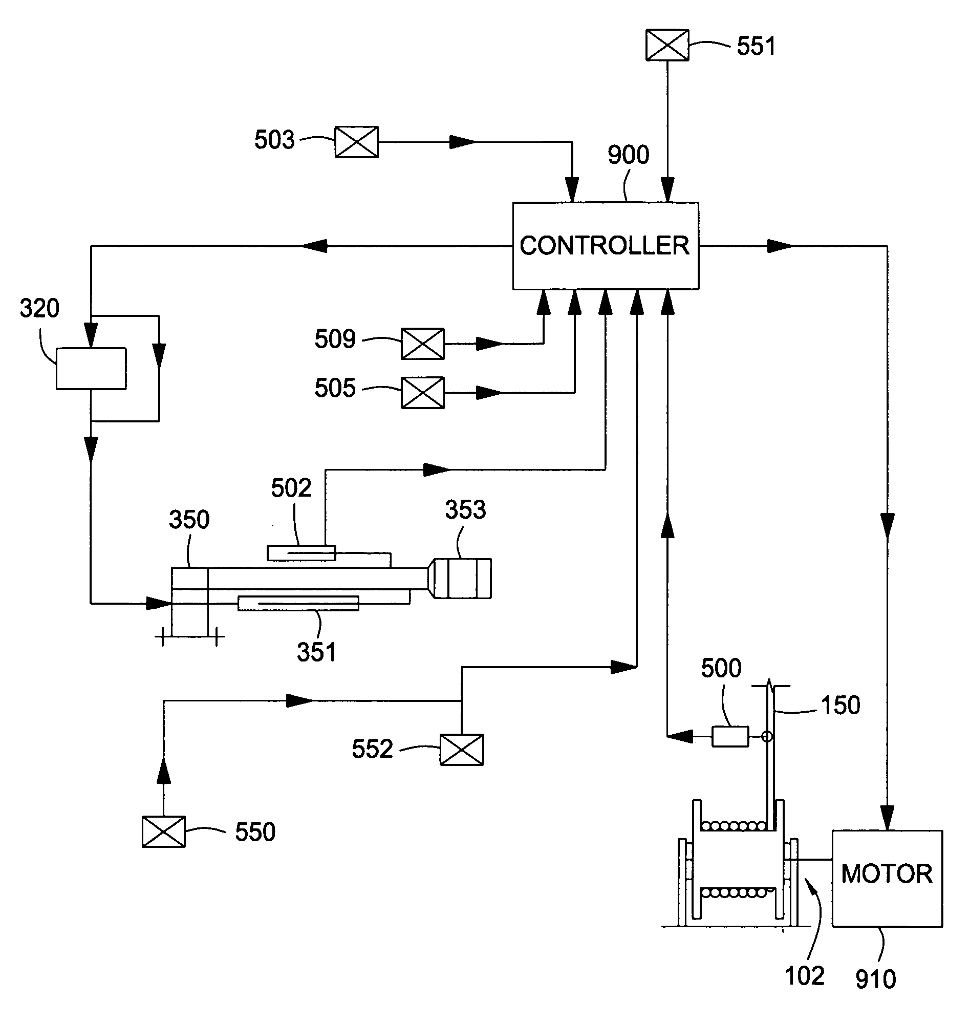
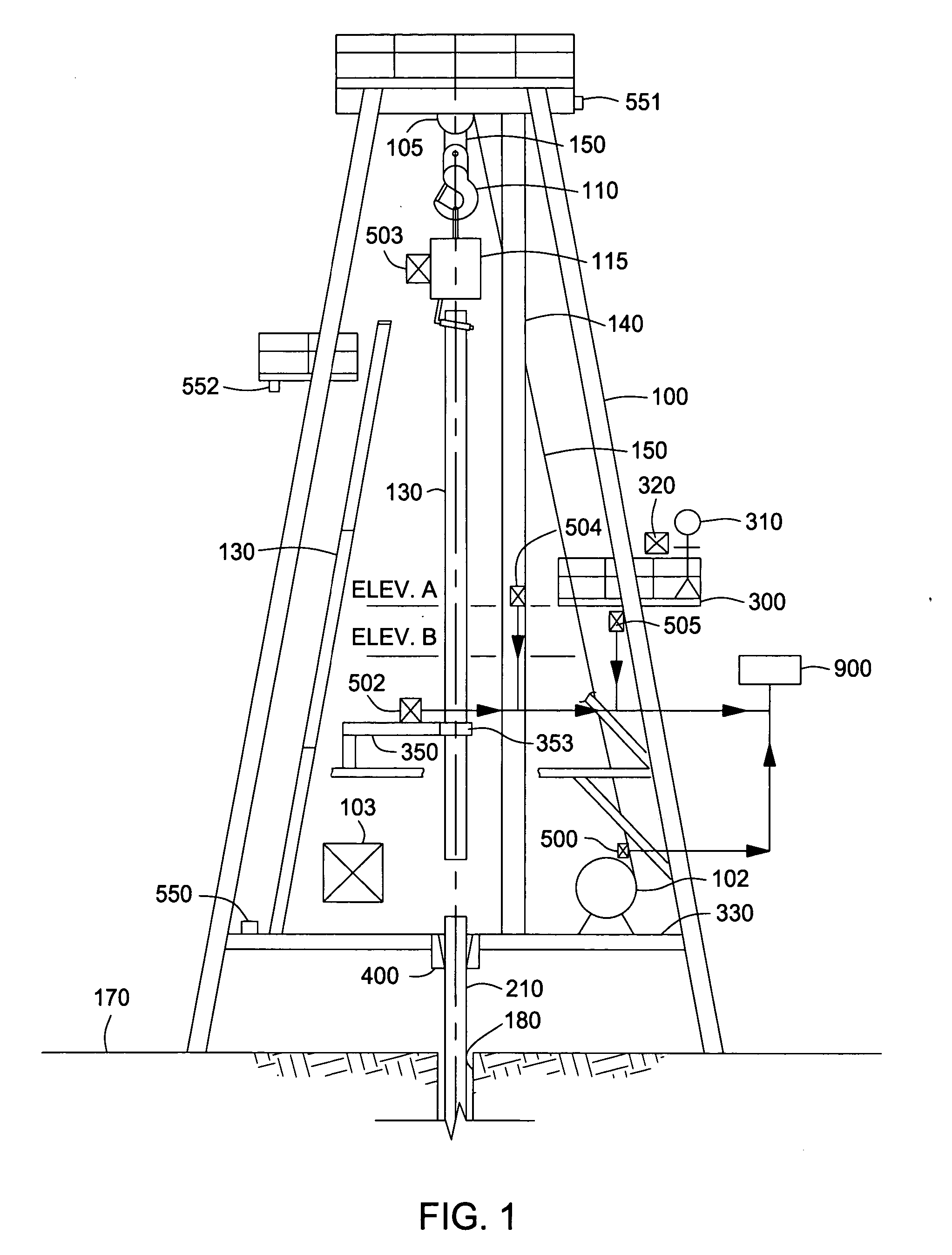
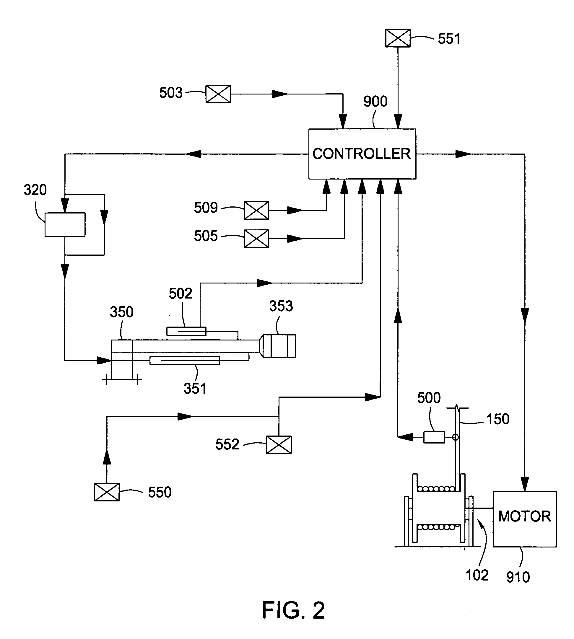
[0019] In one embodiment, a monitor system is provided for use with a drilling rig during assembly and disassembly of tubulars in the ground or subsea surface. The system may by utilized to prevent collisions of drilling rig power tools during tubular assembly and disassembly.

[0020]FIG. 1 illustrates a side view of a drilling rig 100 on a surface 170 above a wellbore 180. The drilling rig 100 includes a draw-works 102 with a cable 150 attached to a pulley system 105, for raising and lowering a hoisting system 115. The hoisting system 115 is shown schematically and could include any type of hoisting system, such that disclosed in U.S. Pat. No. 6,742,596 and U.S. Patent Serial Number 2004 / 0003490 assigned to Weatherford / Lamb, Inc., and herein incorporated by reference in their entirety. The drilling rig 100 further includes a platform 300 with an operator 310 and a control panel 320 to operate one or more tools 350. The platform 300 and operator 310 are located anywhere on the drilli...


PUM


Abstract

Methods and apparatus are provided to prevent collisions between one drilling tool and another drilling tool during drilling operations. If the drilling tools reach a certain proximity to one another, a controller takes action to prevent a collision.

Description

BACKGROUND OF THE INVENTION [0001] 1. Field of the Invention [0002] Embodiments of the present invention generally relate to an apparatus and method for facilitating the connection of tubulars. More particularly, the invention relates to a safety device for preventing well components from colliding. More particularly still, the invention relates to a monitoring system which prevents and / or alerts an operator when a collision between well components is imminent. [0003] 2. Description of the Related Art [0004] In the construction and completion of oil and gas wells, a drilling rig is constructed on the earth's surface to facilitate the insertion and removal of tubular strings into a wellbore. The drilling rig includes a platform and power tools such as a hoisting system, an aligning / stabbing tool and a spider to engage, assemble, and lower the tubulars into the wellbore. The hoisting system suspends above the platform from a pulley that is operated by a draw works that can raise or lo...

Claims


Application Information

Patent Timeline
IPC IPC(8): E21B19/18
CPCE21B44/00E21B19/00E21B19/08E21B19/16E21B19/20G05B11/01G05D3/12E21B19/24
Inventor ABRAHAMSEN, EGILLHOPKINS, CHRISTOPHER
Owner WEATHERFORDLAMB
Why Eureka
Try Eureka