Heat spreader with vapor chamber defined therein and method of manufacturing the same

a heat spreader and vapor chamber technology, which is applied in the direction of electrolysis processes, electroforming processes, etc., can solve the problems of inability to meet the requirements of uniform-type wick structures, the loss of vacuum condition of the heat spreader chamber, and the inability to reliably control the wall thickness of the heat spreader. , to achieve the effect of improving the reliability easy control of the wall thickness of the heat spreader

Inactive Publication Date: 2007-01-25
FU ZHUN PRECISION IND SHENZHEN +1
View PDF3 Cites 16 Cited by
  • Summary
  • Abstract
  • Description
  • Claims
  • Application Information

AI Technical Summary

Benefits of technology

[0008] The present invention relates, in one aspect, to a method for manufacturing a heat spreader. The method includes the following steps: (1) providing a metal foam framework, the metal foam framework having a plurality of pores and defining therein a major space; (2) filling a material into the pores and the major space of the metal foam framework and solidifying the material in the metal foam framework; (3) electrodepositing a layer of metal coating on an outer surface of the metal foam framework; (4) removing the material from the metal foam framework; and (5) filling a working fluid into the major space in the coating layer and hermetically sealing the coating layer to thereby obtain the heat spreader. The heat spreader has therein a wick structure formed of the metal foam framework and a vapor chamber formed of the major space. By this method, the heat spreader is integrally formed and therefore the reliability thereof improved. Also, the wall thickness of the heat spreader can be easily controlled by regulating the time period and the voltage associated with the electrodeposition step.

Problems solved by technology

In addition, the reliability of the heat spreader made by the soldering process is also a problem.
If the heat spreader is in fact not hermetically sealed in the soldering process, the chamber of the heat spreader will gradually lose its vacuum condition.
This uniform-type wick structure cannot satisfy this requirement.
If the condensate is not timely brought back from the second end, the heat pipe will suffer dry-out problem at the first end thereof.

Method used


Image

  • Heat spreader with vapor chamber defined therein and method of manufacturing the same
  • Heat spreader with vapor chamber defined therein and method of manufacturing the same
  • Heat spreader with vapor chamber defined therein and method of manufacturing the same

Examples


Embodiment Construction

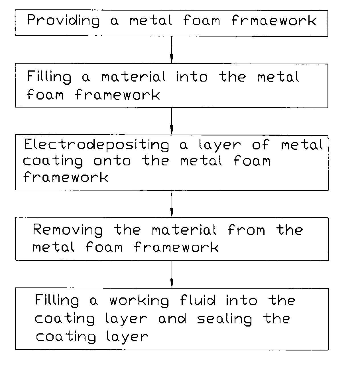
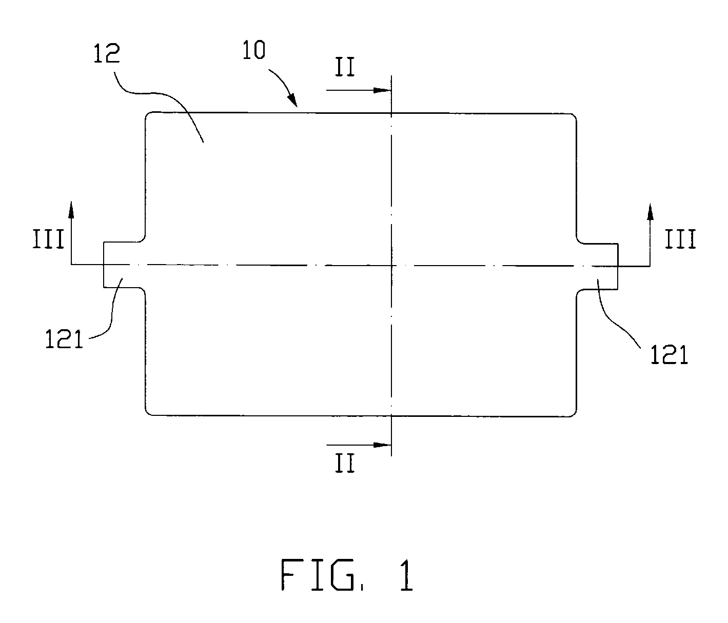
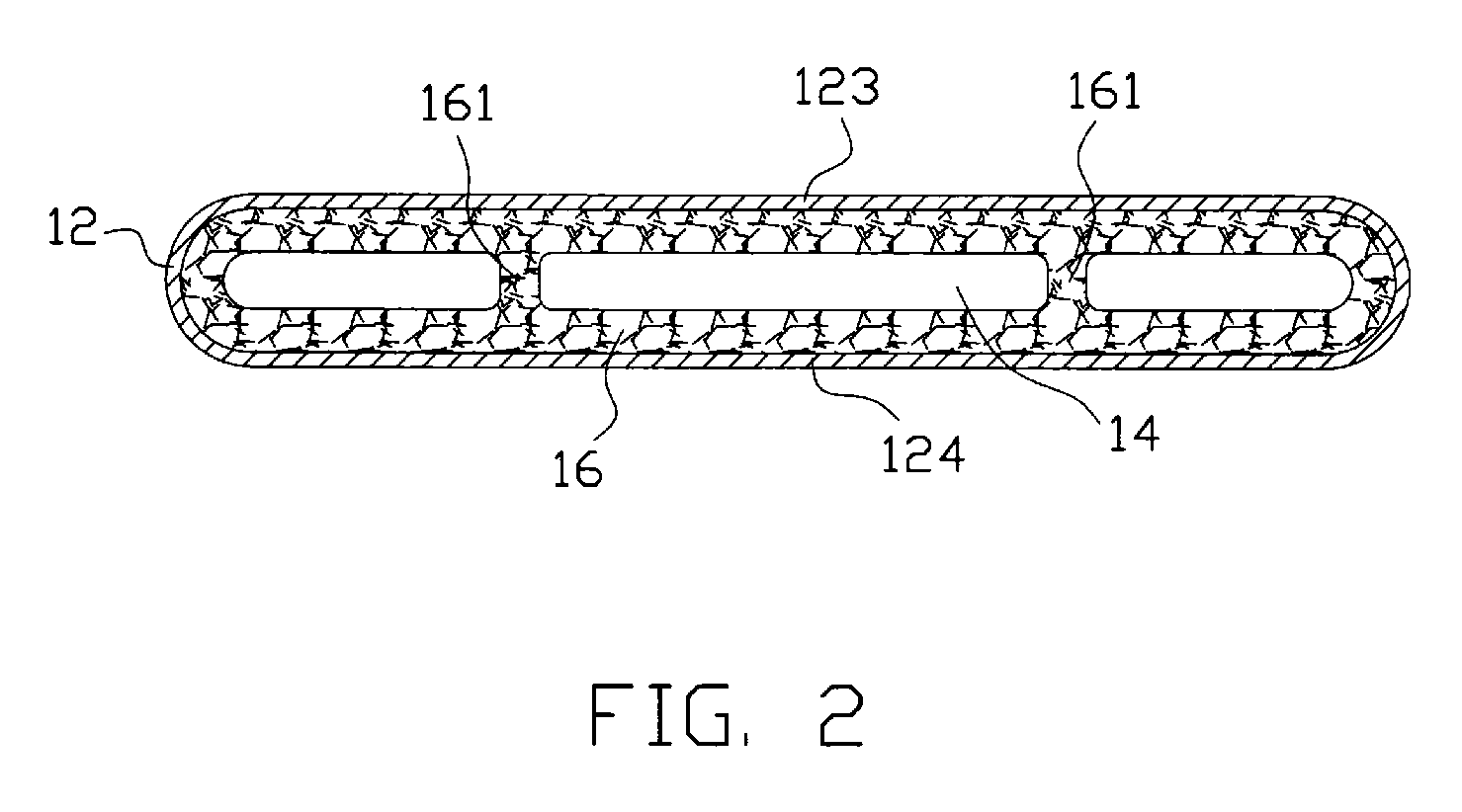
[0022]FIGS. 1-3 illustrate a heat spreader 10 formed in accordance with a method of the present invention. The heat spreader 10 is integrally formed and has a flat type configuration. The heat spreader 10 includes a metal casing 12 with a chamber 14 defined therein. A wick structure 16 is arranged in the chamber 14, lining an inner surface of the metal casing 12 and occupying a portion of the chamber 14. The other portion of the chamber 14, which is not occupied by the wick structure 16 functions as a vapor-gathering region. The wick structure 16 is a porous structure and is in the form of a metal foam. The metal casing 12 is made of high thermally conductive material such as copper or aluminum. The heat spreader 10 has two open distal ends 121 extending from two opposite sides thereof, respectively. A working fluid (not shown) is injected into the chamber 14 through the two open distal ends 121 and then the heat spreader 10 is evacuated and the two distal ends 121 are hermetically ...


PUM

PropertyMeasurementUnit
melting temperatureaaaaaaaaaa
electrically conductiveaaaaaaaaaa
pore sizeaaaaaaaaaa

Abstract

A heat spreader (10) and a method for manufacturing the heat spreader are disclosed. The heat spreader includes a metal casing (12) and a wick structure (16) lines an inner surface of the metal casing. The metal casing defines therein a chamber (14) and includes an evaporating section (126) and a condensing section (127). The wick structure is in the form of metal foam and occupies a portion of the chamber. In one embodiment, the wick structure has a pore size gradually increasing from the evaporating section towards the condensing section of the metal casing. The heat spreader is manufactured by electrodepositing a layer of metal coating (70) on an outer surface of a metal foam framework (20). The metal coating becomes the metal casing and the metal foam framework becomes the wick structure.

Description

FIELD OF THE INVENTION [0001] The present invention relates to an apparatus for transfer or dissipation of heat from heat-generating components, and more particularly to a heat spreader having a vapor chamber defined therein and a method of manufacturing the heat spreader. DESCRIPTION OF RELATED ART [0002] It is well known that heat is generated during normal operations of a variety of electronic components, such as integrated circuit chips of computers. To ensure normal and safe operations, cooling devices such as heat sinks plus electric fans are often employed to dissipate the generated heat away from these electronic components. [0003] As progress continues to be made in electronic industries, integrated circuit chips of computers are made to be more powerful while maintaining an unchanged size or even a smaller size. As a result, the amount of heat generated by these chips is commensurately increased. The heat sinks used to cool these chips are accordingly made larger in order ...

Claims


Application Information

Patent Timeline
Patent Type & Authority Applications(United States)
IPC IPC(8): C25D5/02
CPCC25D1/08C25D5/028C25D5/022
Inventor HWANG, CHING-BAIMENG, JIN-GONG
Owner FU ZHUN PRECISION IND SHENZHEN
Why Eureka
Try Eureka