Liquid spraying assembly

a technology of assembly and liquid, applied in the field of spray guns, can solve the problems of relatively time-consuming, relatively difficult operation, and relatively time-consuming processes, and achieve the effect of reducing the vacuum

Inactive Publication Date: 2007-01-25
YECHOURON SIMON
View PDF7 Cites 35 Cited by
  • Summary
  • Abstract
  • Description
  • Claims
  • Application Information

AI Technical Summary

Benefits of technology

[0019] In a first broad aspect, the invention provides a spraying assembly for spraying a liquid. The spraying assembly includes a reservoir for containing the liquid, the reservoir defining a reservoir outlet; a venting tube defining a tube inlet, a tube outlet substantially opposed to the tube inlet and a tube passageway extending therebetween, the tube inlet being positioned within the reservoir; and a spray gun for spraying the fluid, the spray gun including a gun inlet couplable to the reservoir outlet so as to allow the liquid to flow from the reservoir into the spray gun. The tube outlet is in fluid communication with the exterior of the reservoir, thereby allowing venting the reservoir such as to reduce a vacuum created when the liquid flows out from said reservoir through the reservoir outlet.
[0022] Advantageously, the venting tube allows admitting air into the reservoir while the liquid is supplied to the spray gun so as to allow the liquid to flow into the gun inlet. Because of its configuration, the venting tube allows to admit this air while substantially preventing the risk that the liquid be spilled out of the reservoir when the gun is moved such that the reservoir is not completely vertical.
[0023] In addition, the reservoir is relatively easily removable from the gun as there is no need to then add a cap or any other object to the tube used for venting. Indeed, when an intended user wishes to remove the reservoir from the spray gun, the intended user only orients the reservoir so that the spout points substantially upwardly and detaches the reservoir from the gun. There is no need to add any other component to the reservoir to prevent the paint from spilling.
[0024] In addition, the reservoir and other components of the spraying assembly are relatively easily manufactured at relatively low costs. Also, the spraying assembly is relatively easily used and may be manipulated using relatively simple and ergonomic steps.

Problems solved by technology

However, this process is relatively time consuming as there is a need to attach a paint container into which the first paint is contained to the spray gun each time that a color match test is required.
However, this solution requires that additional material that must be bought by the painter and is relatively environmentally unfriendly as the smaller container is typically disposable.
However, this operation is relatively time-consuming and relatively hard to perform without spilling the paint as the reservoir remains attached to the spray gun 12, which is relatively cumbersome to handle.
Once again, this operation is relatively time-consuming.
While this allows for a relatively fast and easy removal and attachment of the cover 18′ from and to the reservoir 16′, the liquid supply assembly 10′ does not solve the problems of having to thread and unthread the reservoir 16′ to and from the spray gun 12 and of being relatively time-consuming in changing the composition of the paint.
A first disadvantage of this prior art reservoir 16″ is that the plug 36 is a relatively small component that is relatively easily lost or misplaced.
Also, adding and removing the plug 36 from the air vent 34 adds additional steps that need to be remembered and that are relatively time-consuming.
In addition, there is a risk that while in use, the spray gun is oriented so that paint may flow out of the reservoir 16″ through the air vent 34 and fall onto the object to be painted.

Method used


Image

  • Liquid spraying assembly
  • Liquid spraying assembly
  • Liquid spraying assembly

Examples


Embodiment Construction

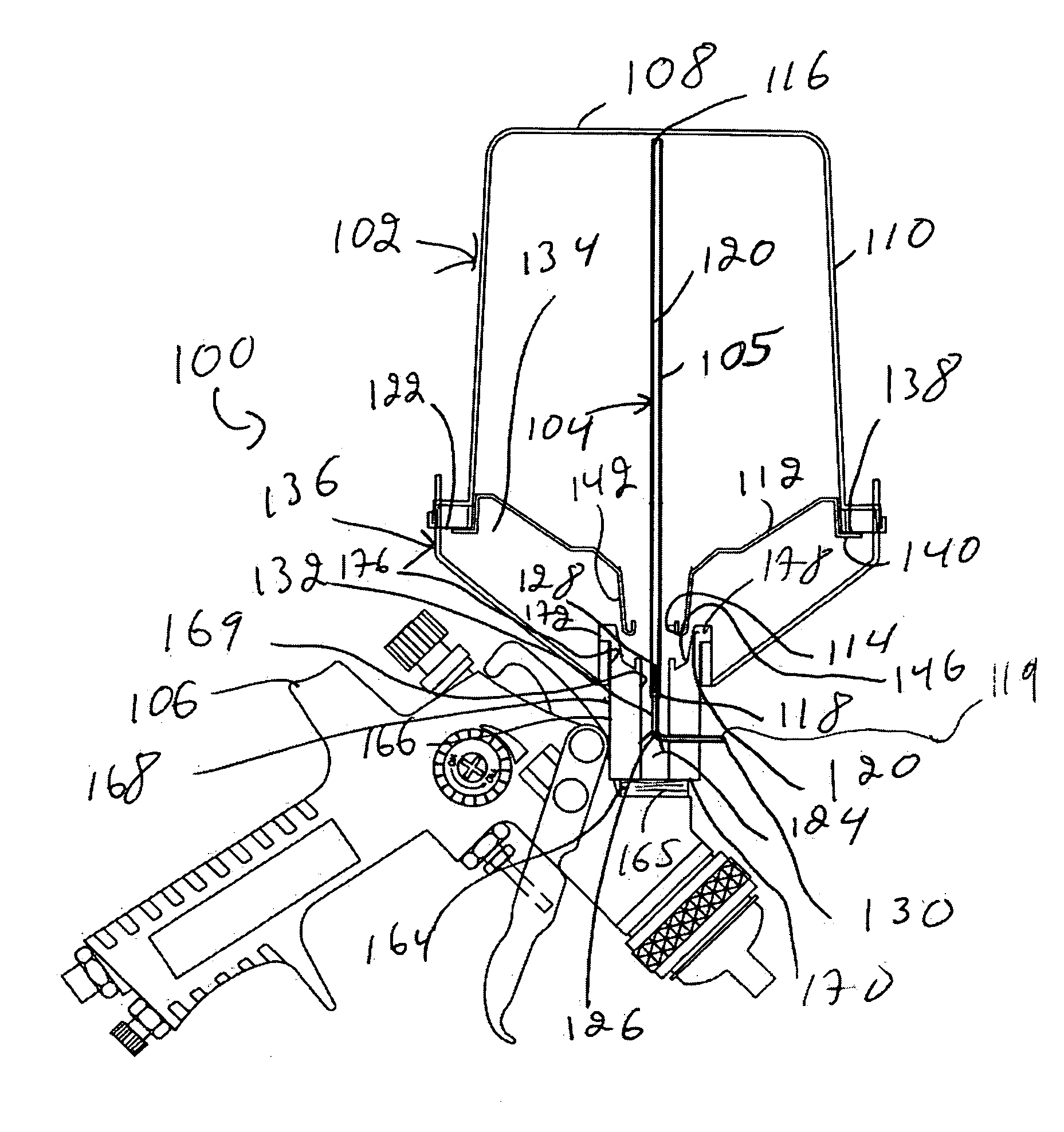
[0043]FIG. 4 illustrates a spraying assembly 100 for spraying a liquid (not shown in the drawings). The spraying assembly 100 includes a reservoir 102 for containing the liquid. The spraying assembly 100 also includes a venting tube 104, which extends, at least in part, within the reservoir 102. Furthermore, the spraying assembly 100 includes a spray gun 106 for spraying the fluid. The reservoir 102 includes a reservoir outlet couplable to the spray gun 106 so as to allow the liquid to flow from the reservoir 102 into the spray gun 106.

[0044] The venting tube 104 defines a tube inlet 116, a tube outlet 119 substantially opposed to the tube inlet 116 and a tube passageway 120 extending therebetween. The tube inlet 116 is positioned within the reservoir 102 and the tube outlet 119 is in fluid communication with the exterior of the reservoir 102, thereby allowing venting the reservoir 102 such as to reduce a vacuum created when the liquid flows out from the reservoir 102 through the r...


PUM


Abstract

A spraying assembly for spraying a liquid. The spraying assembly includes a reservoir for containing the liquid, the reservoir defining a reservoir outlet; a venting tube defining a tube inlet, a tube outlet substantially opposed to the tube inlet and a tube passageway extending therebetween, the tube inlet being positioned within the reservoir; and a spray gun for spraying the fluid, the spray gun including a gun inlet couplable to the reservoir outlet so as to allow the liquid to flow from the reservoir into the spray gun. The tube outlet is in fluid communication with the exterior of the reservoir, thereby allowing venting the reservoir such as to reduce a vacuum created when the liquid flows out from said reservoir through the reservoir outlet.

Description

[0001] This application claims priority from U.S. Provisional Patent Application Ser. No. 601700,313 filed Jul. 19, 2005.FIELD OF THE INVENTION [0002] The present invention relates to the general field of spray guns and is particularly concerned with a liquid spraying assembly. BACKGROUND OF THE INVENTION [0003] In many industries, such as for example in the automotive collision repair industry, there is often a need to spray a liquid, such as paint, on only part of an object using a spray gun. Since the object, for example a car, is often already at least in part painted, a painter needs to insure that the newly painted portions are of substantially the same color as the already painted portions of the object. This process is known in the art as color matching. [0004] Typically, paint of an approximately suitable color is mixed according to a predetermined recipe to produce a first paint. Then, part of the object to be painted is sprayed with this first paint and the resulting colo...

Claims


Application Information

Patent Timeline
Patent Type & Authority Applications(United States)
IPC IPC(8): A01G25/14
CPCB05B7/2478B05B7/2408
Inventor YECHOURON, SIMON
Owner YECHOURON SIMON
Why Eureka
Try Eureka