3D image reconstructing method for a positron CT apparatus, and positron CT apparatus

a positron ct and reconstruction method technology, applied in the field of 3d image reconstruction method for a positron ct apparatus, can solve the problems of inability to accurately reconstruct the image, large amount of data stored, and long time taken, so as to avoid the difference in the number of times of sinogram addition, eliminate the non-uniformity of data, and improve the effect of image quality

Inactive Publication Date: 2007-01-25
SHIMADZU CORP
View PDF6 Cites 34 Cited by
  • Summary
  • Abstract
  • Description
  • Claims
  • Application Information

AI Technical Summary

Benefits of technology

[0027] In the method and apparatus according to this invention, it is preferred that a number of times of addition difference correction process is performed, before or during the 3D iterative reconstruction, for eliminating non-uniformity of data due to differences in the number of times of sinogram addition in 3D data acquisition. In this way, image quality deterioration due to differences in the number of times of sinogram addition may be avoided.

Problems solved by technology

However, the sinograms acquired through 3D data acquisition constitute an immense amount of data.
The amount of data stored is inevitably huge, and a long time is taken from the start of an examination to the end of imaging.
However, the above PET apparatus tends to cause image quality deterioration due to a drop in resolution and lowering of S / N ratio.
Since this conventional positron apparatus converts 3D data into 2D data, it is difficult to avoid a drop in resolution due to errors occurring with the conversion from 3D data to 2D data.
Further, since images are reconstructed from the 2D data, the apparatus cannot directly use 3D data physical models such as detector response, attenuation correction and statistical property in time of image reconstruction.
The apparatus has limitations for improvement in the S / N ratio of reconstructed images.

Method used


Image

  • 3D image reconstructing method for a positron CT apparatus, and positron CT apparatus
  • 3D image reconstructing method for a positron CT apparatus, and positron CT apparatus
  • 3D image reconstructing method for a positron CT apparatus, and positron CT apparatus

Examples


Embodiment Construction

[0038] A preferred embodiment of this invention will be described in detail hereinafter with reference to the drawings.

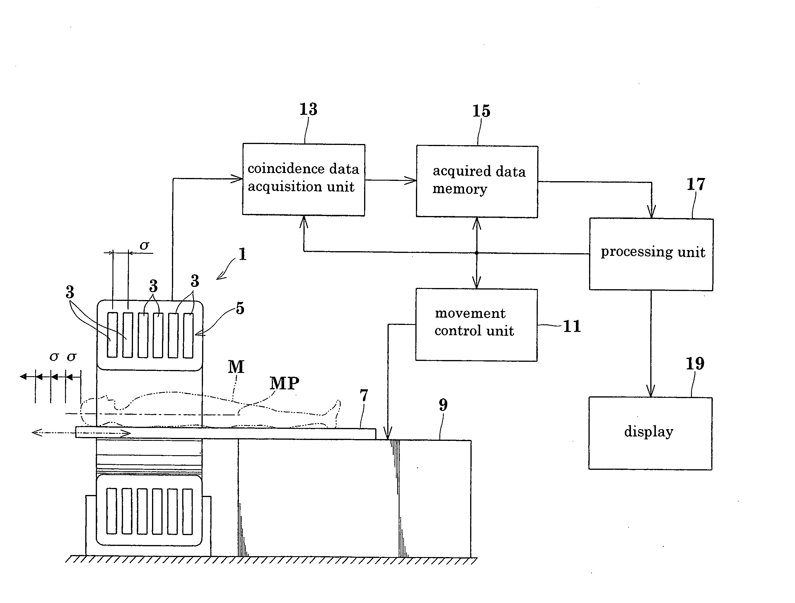
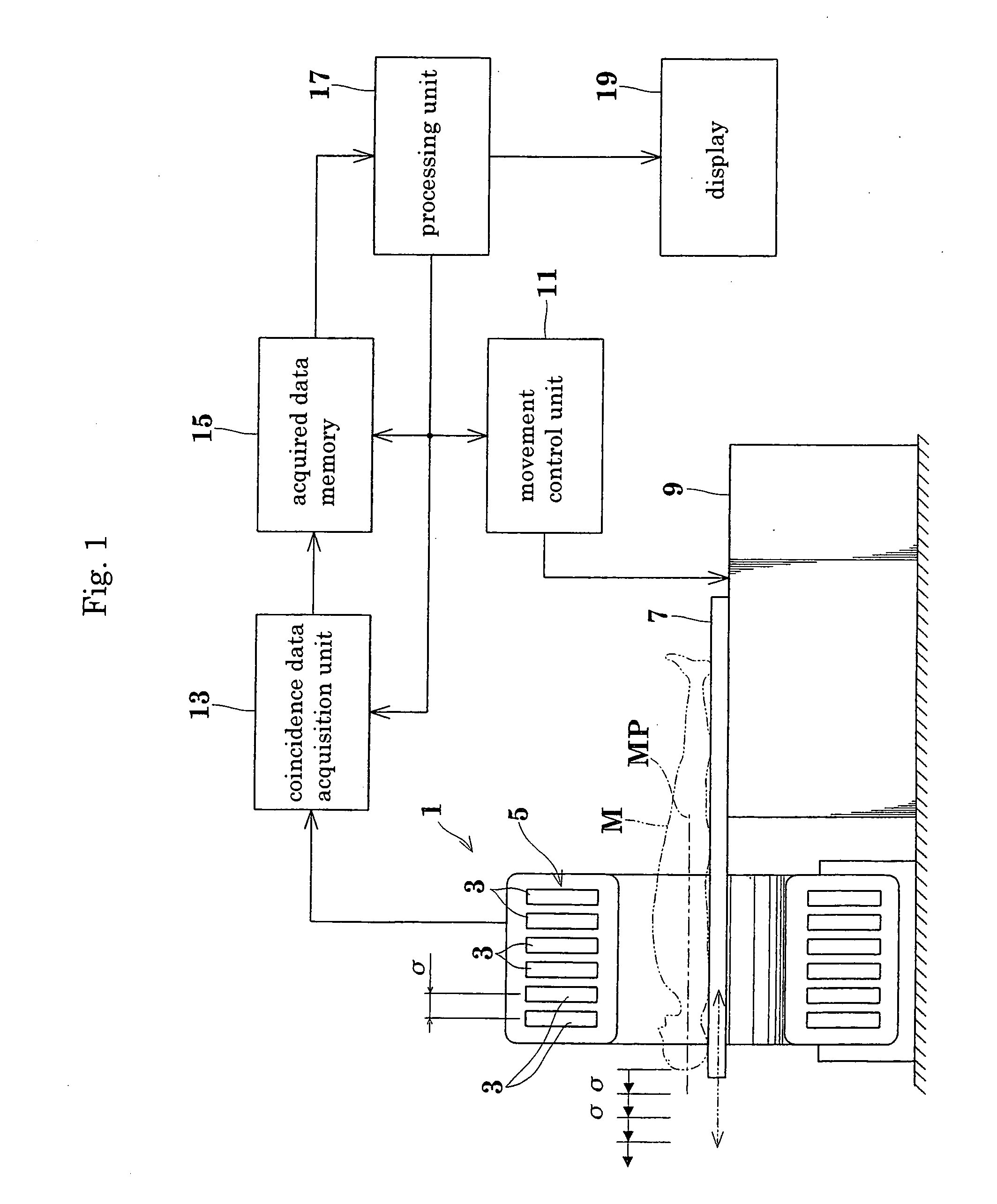
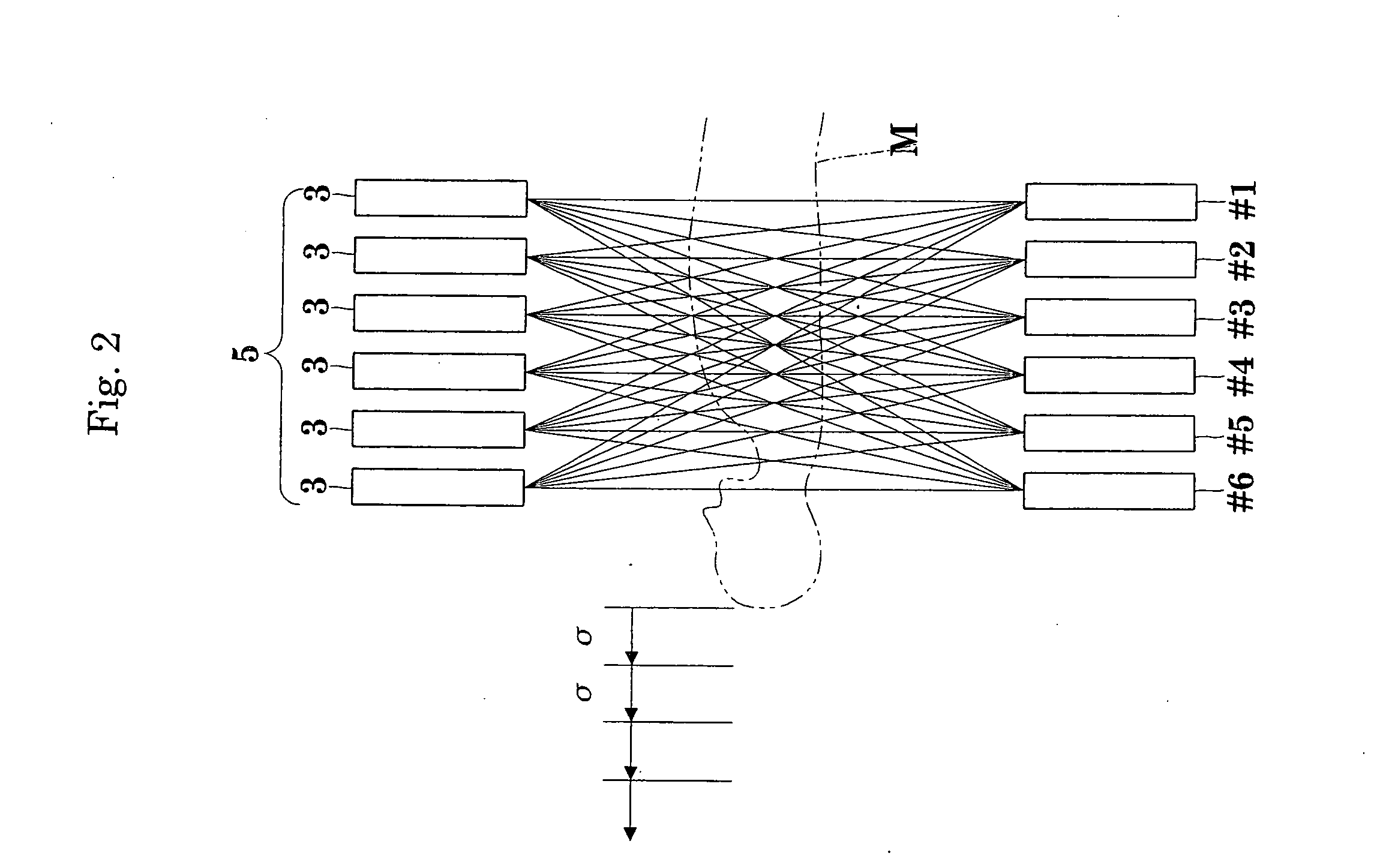
[0039] A method and an apparatus according to this invention will be described with reference to the drawings. FIG. 1 is a block diagram showing an outline of a PET apparatus according to this invention. FIG. 2 is a schematic view showing a positional relationship between movement of an object under examination and a multi-ring detector in the PET apparatus.

[0040] The PET apparatus according to the invention includes a gantry 1 having a center opening and ring detectors 3 in the form of radiation detectors arranged in ring form. A multi-ring detector 5 has, for example, ring type radiation detectors 3 forming six rings (#1 to #6) arranged along the axis of the opening of the gantry 1.

[0041] Arranged in front of the gantry 1 are a bed 7 movable back and forth (in and out) relative to the opening of the gantry 1, and a bed moving device 9 for moving the bed 7 back ...


PUM


Abstract

Image quality deterioration due to a drop in resolution or lowering of S/N ratio while reducing the amount of data stored during a 3D data acquisition process, and shortening the time from the start of an examination to the end of imaging. The method and apparatus of this invention perform, in parallel with the 3D data acquisition process, addition of sinograms, reading of subsets of the sinograms having been added, and image reconstruction. Consequently, the amount of data stored is reduced, and the time from the start of an examination to the end of imaging is shortened. At the same time, since 3D iterative reconstruction is not accompanied by conversion from 3D data to 2D data, a drop in resolution due to errors occurring with the conversion from 3D data to 2D data is avoided. The 3D iterative reconstruction can directly incorporate processes such as an attenuation correction process. It is thus possible to avoid also a lowering of S/N ratio resulting from an indirect incorporation of such processes.

Description

BACKGROUND OF THE INVENTION [0001] (1) Field of the Invention [0002] This invention relates to a 3D image reconstructing method for a positron CT apparatus (hereinafter referred to as “PET apparatus” as appropriate) and to a positron CT apparatus for acquiring sinograms for each combination of ring pairs by detecting coincidence counting data of the ring pairs in each moving position, while moving a multi-ring detector having ring type detectors arranged in an axial direction and a bed having an object under examination placed thereon, relative to each other axially of the multi-ring detector, and performing 3D image reconstruction for RI distribution image reconstruction based on these sinograms. Especially, the invention relates to a technique for improving the quality of RI distribution images. [0003] (2) Description of the Related Art [0004] Conventionally, a PET apparatus that performs an image reconstruction process for RI distribution images based on sinograms acquired throug...

Claims


Application Information

Patent Timeline
Patent Type & Authority Applications(United States)
IPC IPC(8): G01T1/161
CPCG01T1/2985G01T1/1611
Inventor KITAMURA, KEISHI
Owner SHIMADZU CORP
Why Eureka
Try Eureka