Strip brush seal

a brush seal and strip brush technology, applied in the direction of liquid fuel engines, machines/engines, mechanical equipment, etc., can solve the problems of loss of elasticity, difficulty in achieving a seal against fluid, and worsening the seal capability, so as to avoid wear and improve the seal capability

Active Publication Date: 2007-01-25
MITSUBISHI HEAVY IND LTD
View PDF9 Cites 24 Cited by
  • Summary
  • Abstract
  • Description
  • Claims
  • Application Information

AI Technical Summary

Benefits of technology

[0017] The fluid pressure which acts on a space with a triangular cross section formed by the circumference of the rotary shaft and the lifting portion; provides a lifting force against the lifting portion so as to lift the lifting portion off the circumference of the rotary shaft forming a minute gap therebetween. When the lifting portion floats relative to the circumference of the rotary shaft, the fluid starts to flow from the free end of the rotary shaft toward the inter strip gap of the seal strip which is located adjacently forward in the direction of rotation. As a result a small gap is formed between the free end of the lifting portion and the circumference of the rotary shaft. At the same time a pressure increase at the free end of the lifting portion also leads to a pressure increase between the circumference of the rotary shaft and the inner diameter surface of the back plate, which effectively prevents the fluid from leaking through the gap between the circumference of the rotary shaft and the inner diameter surface of the back plate toward a low pressure region. The lifting portion therefore provides not only an effect for avoiding wear against the circumference of the rotary shaft but also another effect for improving the seal capability by increasing the inter surface pressure in the lifting portion.

Problems solved by technology

The large fit clearance makes it difficult to effect a seal against the fluid.
As a result the strip brush 109 substantially loses its elasticity and increasing wear of the strip brush 109 widens the clearance gap, which even worsens the seal capability.
Furthermore the step 130 on the thin strip brush 109, which requires precision machining, is not straightforward to manufacture.
Use of the step 130 thus increases a machining cost and increases the production cost of the strip brush 109 after all.
Also disposing the tiny step 130 on the thin strip brush 109 alone can hardly exhibit a practical, lifting force.
Fabricating the step 130 on an extremely thin strip imposes another technical difficulty.

Method used


Image

  • Strip brush seal
  • Strip brush seal
  • Strip brush seal

Examples


second embodiment

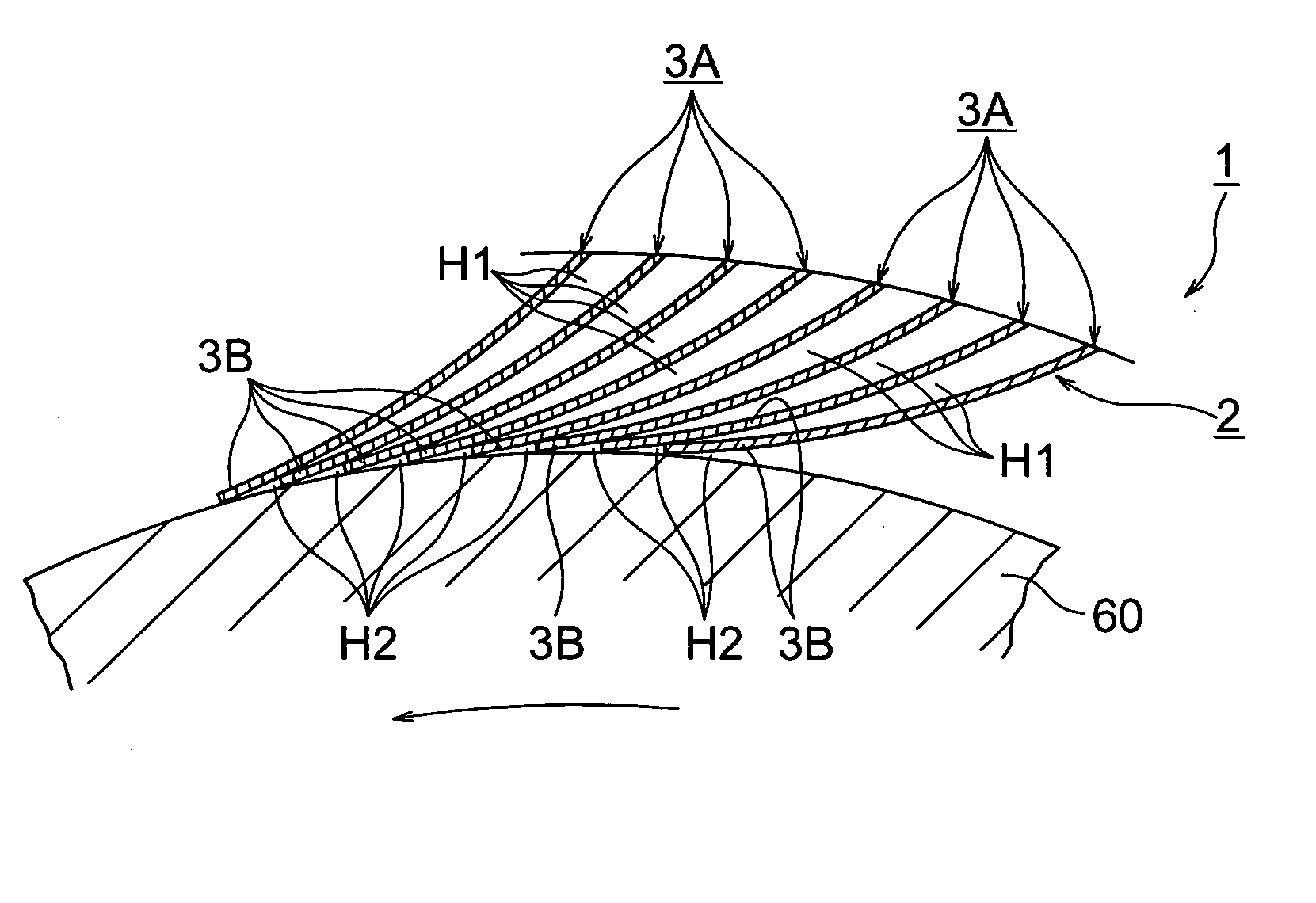
[0073] In a strip brush seal device 1 of a second embodiment related to the present invention, the lifting portion is defined as a lifting strip and a lifting strip 3B retains a lifting means 10 at the free end of the lifting strip 3B.

[0074] In the strip brush seal device 1 of a second embodiment related to the present invention, as the notch-shaped lifting means 10 is disposed at the free end of the lifting strip 3B as shown in FIG. 12 a fluid entering the inter strip gap of a stoppage portion 3A continues to flow toward the free end tip of the lifting strip 3B and then flows through the lifting means 10 into an adjacent inter strip gap which is formed between the current seal strip 3 and adjacent seal strip 3 being located adjacently forward. The fluid pressure in this case acts on so as to lift the lifting strip 3B. Pressure distributions under this circumstance acts on in a uniform manner like PB of FIG. 13, FIG. 16 and FIG. 18.

[0075] The lifting force distribution becomes of a...

third embodiment

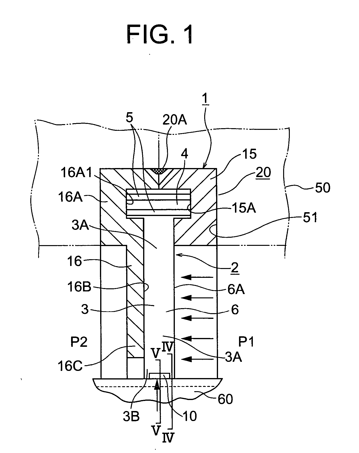
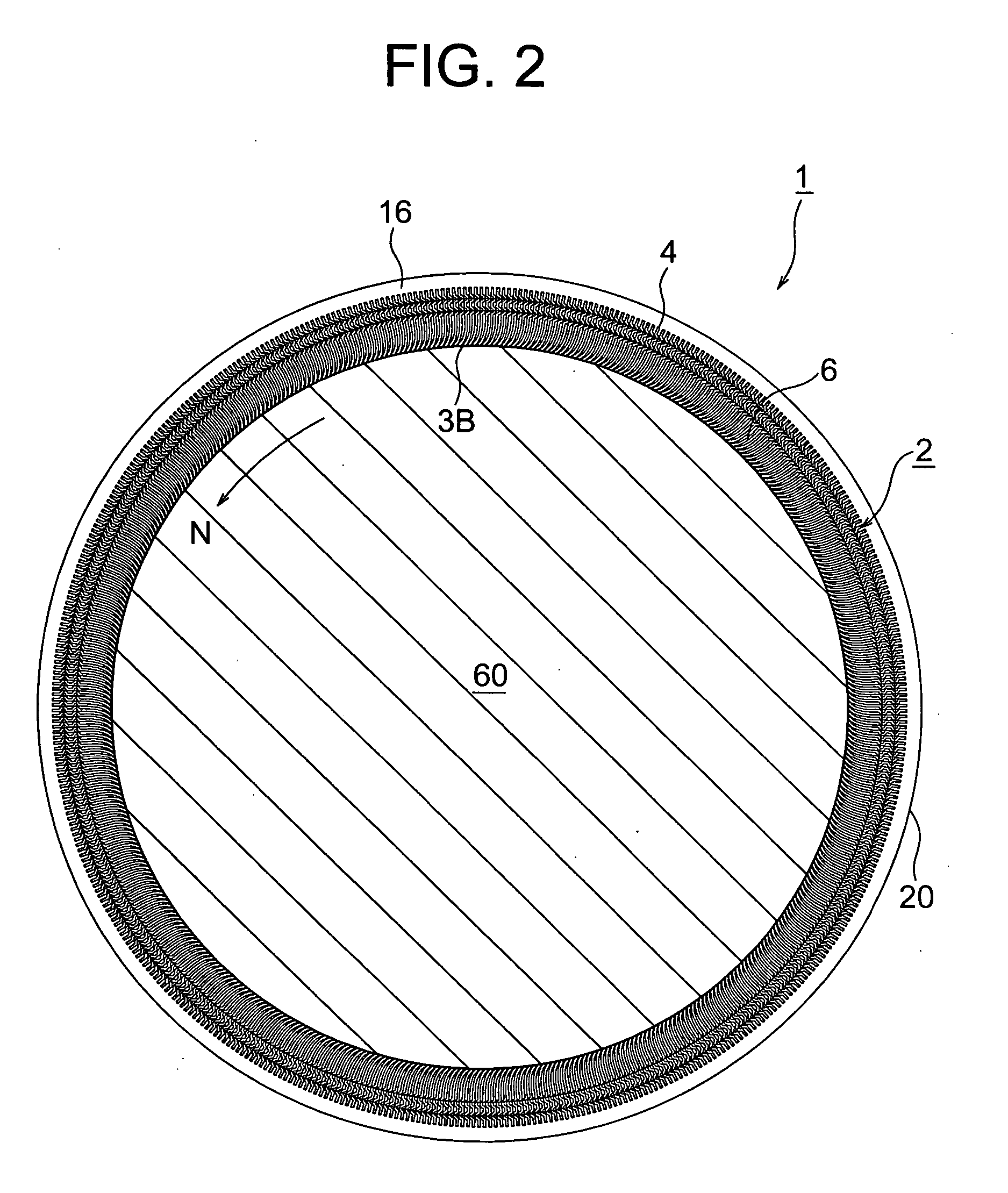
[0076] A strip brush seal device 1 of a third embodiment related to the present invention retains a spacer portion for providing an inter strip gaps to a seal strip 3 in an outer circumferential mounting portion 4 and the free end surface of an inner circumferential lifting portion 3B is disposed in an abutting relation or in close proximity with a rotary shaft 60.

[0077] In the strip brush seal device 1 of a third embodiment related to the present invention, when the seal strips 3 are disposed around the rotary shaft 60 to form an annularly shape and the adjacent strip surfaces of the seal strips 3 located toward the seal portion 6 side lightly abut with each other or come in close proximity relative to each other, a mounting portion 4 side necessarily becomes large in diameter and a gap remains between the arranged surfaces. Choosing the height of the spacer portion 5 according to the remaining inter strip gap leads to a straightforward manufacture of the annularly shape of the mou...

fourth embodiment

[0079] A strip brush seal device 1 of a fourth embodiment related to the present invention retains a seal strip 3 of a seal portion 6 being arranged gradually thinner as it approaches the free end tip thereof.

[0080] In the strip brush seal device 1 of the fourth embodiment related to the present invention, since the thickness of the seal strip 3 gradually decreases as it approaches the free end tip, the lifting portion 3B can exhibit a substantial elastic deformation and improve a lifting capability thereof. Also as the inter strip gap of the seal portion 6 can be arranged small an inhibition (seal) effect of the seal portion 6 against the fluid can be improved. In case of a strip brush seal 2 of a small diameter, in particular, a longitudinal length of the seal strip 3 becomes small. Gradually thinning the seal strip 3 in a direction toward the lifting portion 3B provides a substantial lifting capability of the lifting portion 3B even for the seal strip 3 of a short length. The lif...


PUM


Abstract

A primary technical goal of this strip brush seal device is to prevent friction of a lifting portion of a seal portion against the circumference of a rotary shaft and to improve the seal capability thereof. In the strip brush seal device, each seal strip in a seal portion forms a stoppage portion in the radially outward portion thereof and a lifting strip in the radially inward portion thereof wherein the lifting strip is inflected toward the rotational direction of the rotary shaft at a second angle (θ) to the tangential direction of the circumference of the rotary shaft and the second angle (θ) is in the range of from 0 to 40 degrees.

Description

BACKGROUND OF THE INVENTION [0001] 1. Field of the Invention [0002] The present invention relates generally to a strip brush seal arrangement to effect a seal between a rotary shaft of a compressor, gas turbine engine, refrigerator, pump or the like, and a housing containing the rotary shaft therein. More particularly, this invention relates to a technical domain of strip brush seals in which a lifting portion located the free end side of the seal portion is arranged at an angle relative to the diameter surface of the rotary shaft in order to increase a lifting force and to decrease friction under relative movements. [0003] 2. Description of the Related Art [0004] Related art of the present invention is found in U.S. Pat. No. 6,343,792, which discloses a strip brush seal device 100 as shown in FIG. 21. In the strip brush seal device 100 of FIG. 21, a plurality of circularly bent, thin strip brushes 109, also called “leaves”, are arranged along the circumference of a rotary shaft 120...

Claims


Application Information

Patent Timeline
Patent Type & Authority Applications(United States)
IPC IPC(8): F01D11/02F01D11/00F01D25/16F04C27/00F04D29/10F16J15/22F16J15/3288
CPCF16J15/3292
Inventor KONO, TORU
Owner MITSUBISHI HEAVY IND LTD
Why Eureka
Try Eureka