Drive apparatus
Inactive Publication Date: 2007-01-25
CANON KK
View PDF11 Cites 2 Cited by
Summary
Abstract
Description
Claims
Application Information
AI Technical Summary
This helps you quickly interpret patents by identifying the three key elements:
Problems solved by technology
Method used
Benefits of technology
[0030] It is an object of the present invention to provide a drive apparatus which is small in size, short in axial length, low in cost, and high in output.
Problems solved by technology
Since the shorter the distance, the more easily a magnetic flux can flow, most of magnetic fluxes pass through the vicinity of root portions of the short and long yokes which do not face the outer peripheral surface of the magnet, resulting in unsatisfactory magnetic efficiency and low output.
For this reason, when an attempt is made to reduce the outer diameter of the stepping motor, a range in which the outer magnetic pole portions are opposed to the outer peripheral surface of the magnet is limited (i.e., there is a wide area of the outer periphery of the magnet to which the outer magnetic pole portions are not opposed), resulting in reduced output.
H09-331666 and 2003-023763 are each required to have a predetermined gap between the inner peripheral surface of the magnet and the inner magnetic pole portions opposed thereto, and the gap management at the manufacturing process results in increase in costs.
On the other hand, it is difficult to integrally construct the inner magnetic pole portions and the outer magnetic pole portions in the part manufacturing process.
If these magnetic pole portions are manufactured separately and thereafter, integrally assembled, the number of parts is increased and cost is increased.
H10-62836 is short in axial length, it is constructed to include a connecting yoke that connects the two yoke members together, and hence the number of parts is increased and cost is high.
In addition, magnetic efficiency is poor in actual since a magnetic loss occurs due to connection of the yokes.
For this reason, magnetic efficiency is poor.
Method used
Image
Click on the blue label to locate the original text in one second.
Reading with bidirectional positioning of images and text.
Examples
first embodiment
[0062] First, a description will be given of a drive apparatus according to the present invention.
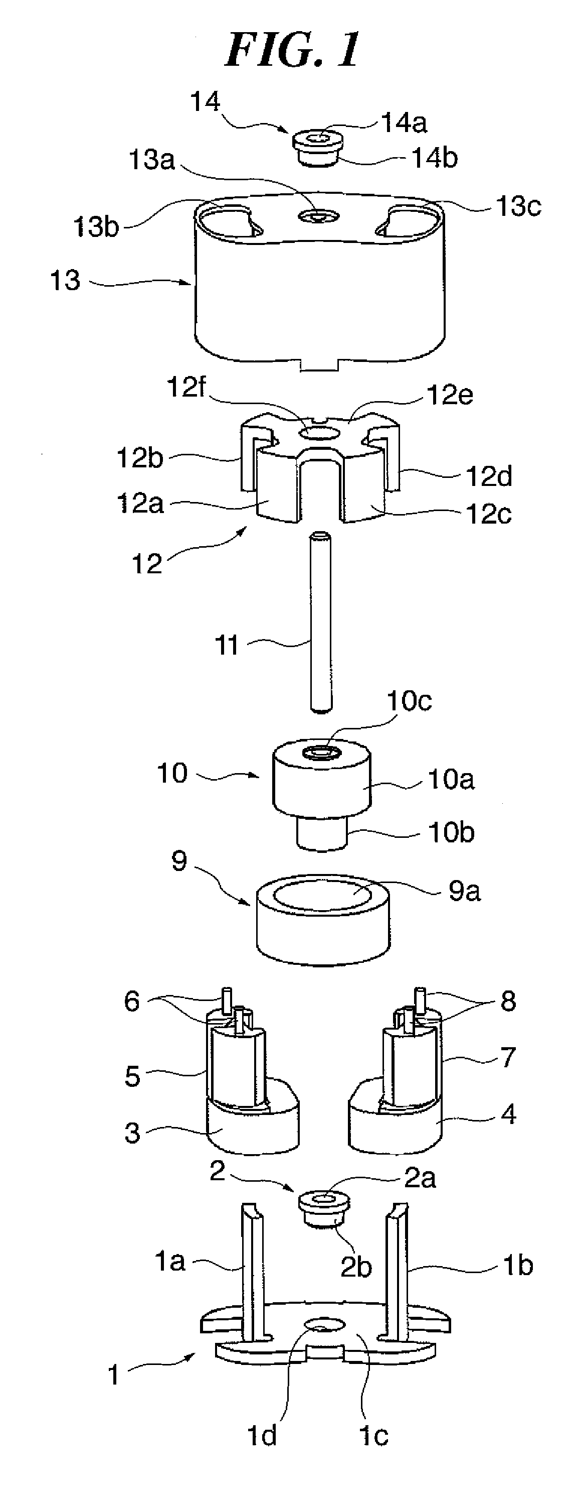
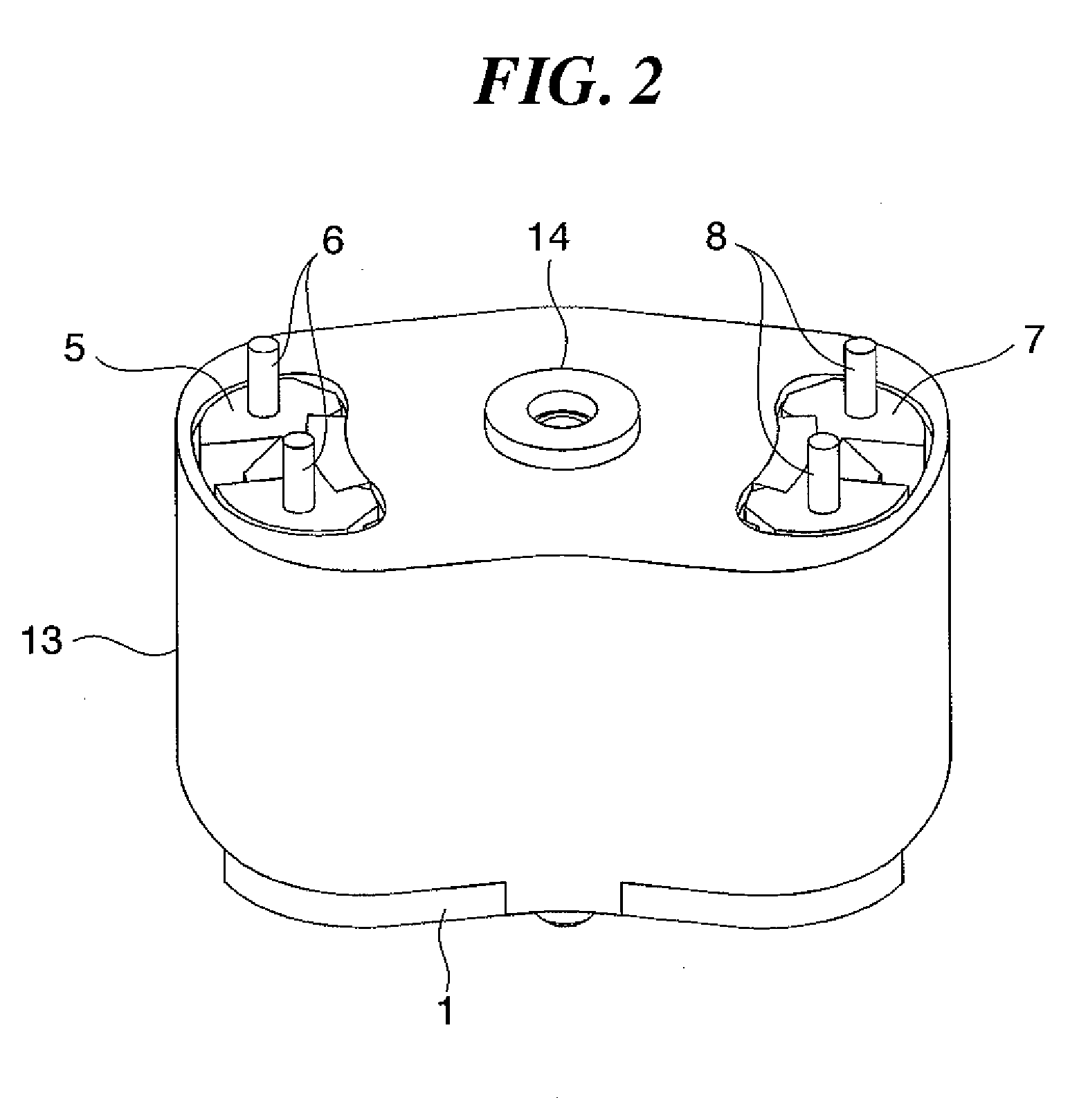
[0063]FIG. 1 is an exploded perspective view showing a stepping motor which is a drive apparatus according to the first embodiment. FIG. 2 is a perspective view showing the stepping motor in FIG. 1 in an assembled state. FIG. 3 is a perspective view showing the stepping motor in FIG. 1 with its cover omitted. FIG. 4 is a longitudinal sectional view showing the internal construction of the stepping motor.
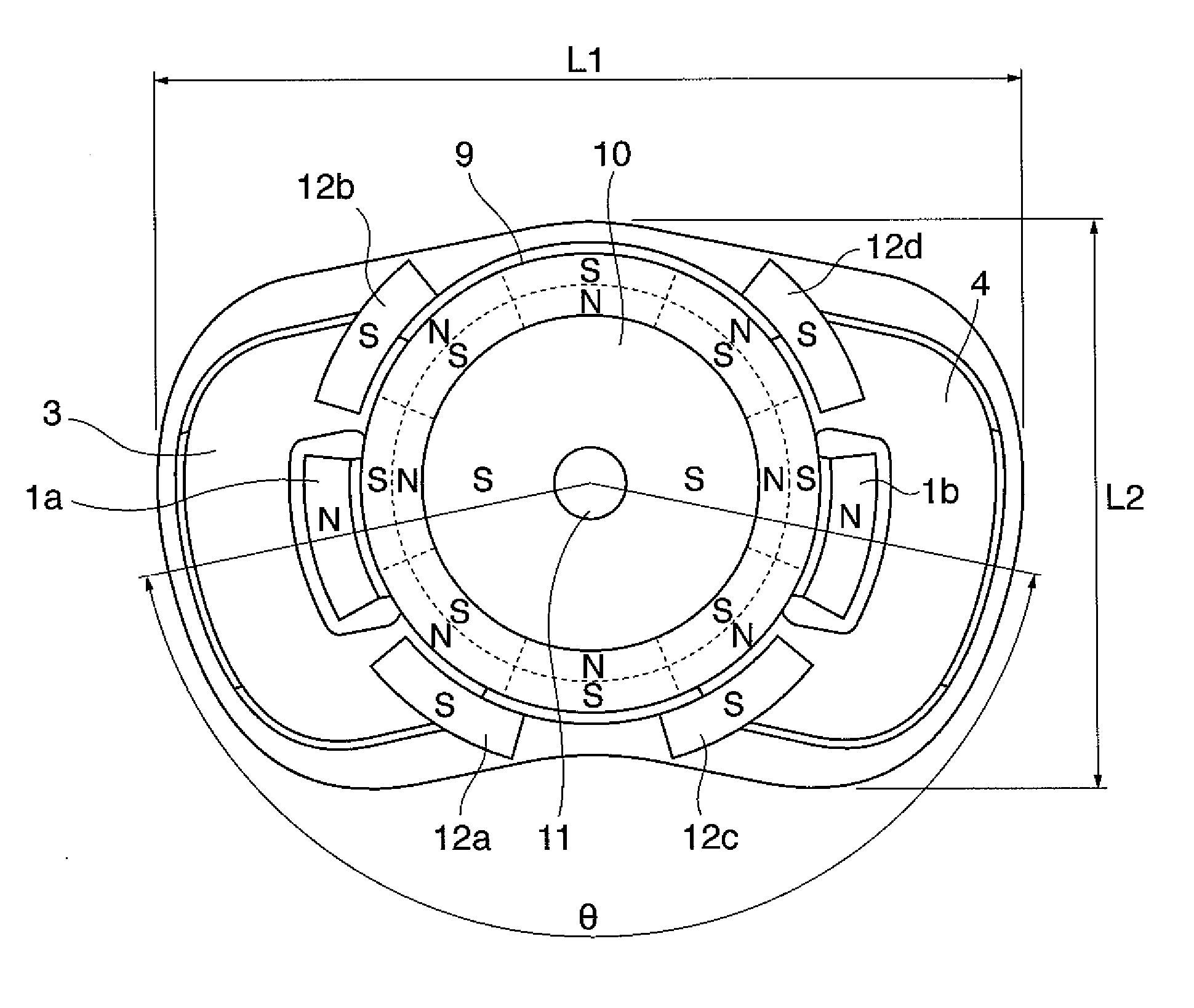
[0064] As shown in FIGS. 1 to 4, the stepping motor is comprised of a first stator 1, a first bearing 2, a first coil 3, a second coil 4, a first bobbin 5, a second bobbin 7, a magnet 9, a core 10, a rotary shaft 11, a second stator 12, a cover 13, and a second bearing 14.
[0065] The first stator 1 is made of a soft magnetic material and is comprised of a first outer magnetic pole portion 1a, a second outer magnetic pole portion 1b, and a flat plate portion 1c formed integrally with bot...
second embodiment
[0146] A description will now be given of a drive apparatus according to the present invention.
[0147]FIG. 9 is an exploded perspective view showing a stepping motor which is the drive apparatus according to the second embodiment. FIG. 10 is a perspective view showing the stepping motor in an assembled state. FIG. 11 is a perspective view showing the stepping motor with its bobbin omitted. FIG. 12 is a longitudinal sectional view showing the internal construction of the stepping motor.
[0148] As shown in FIGS. 9 to 12, the stepping motor is comprised of a first stator 21, a first bearing 22, a first coil 23, a second coil 24, a bobbin 25, a magnet 29, a rotor 30, a second stator 32, and a second bearing 34.
[0149] The present embodiment differs from the first embodiment described above in that the core 10 and the rotary shaft 11 are not manufactured separately and then fixed to each other, but the rotor 30 comprised of a core and a rotary shaft formed integrally with each other in ad...
PUM
Abstract
A drive apparatus which is small in size, short in axial length, low in cost, and high in output. A stepping motor as the driving apparatus includes a first coil, a second coil, a magnet, and a rotor comprised of a core and a rotary shaft. First through fourth outer magnetic pole portions are opposed to the outer peripheral surface of the magnet with a predetermined gap therebetween. The first and the second coils are disposed adjacent to the magnet axially of the rotary shaft and disposed at respective ends of the rotary shaft. The first and second outer magnetic pole portions are inserted inside the first and second coils, respectively. As viewed in the circumferential direction of the magnet, the third and fourth outer magnetic pole portions are disposed close to the first and second outer magnetic pole portions, respectively.
Description
BACKGROUND OF THE INVENTION [0001] 1. Field of the Invention [0002] The present invention relates to a drive apparatus, and more particularly, to a drive apparatus suitable to realize a small-sized stepping motor with increased output. [0003] 2. Description of the Related Art [0004] Conventionally, stepping motors have been widely used as driving sources for various apparatuses. As a first conventional example, there has been proposed a stepping motor which has a small diameter centering on a rotary shaft of the motor and has high output (see Japanese Laid-Open Patent Publication (Kokai) No. H09-331666, for example). [0005]FIG. 13 is an exploded perspective view showing the construction of the stepping motor according to the first conventional example, and FIG. 14 is a longitudinal sectional view showing the internal construction of the stepping motor in an assembled state. [0006] As shown in FIGS. 13 and 14, the stepping motor is comprised of a first stator 204, a second stator 205...
Claims
Application Information
Patent Timeline
Application Date:The date an application was filed.
Publication Date:The date a patent or application was officially published.
First Publication Date:The earliest publication date of a patent with the same application number.
Issue Date:Publication date of the patent grant document.
PCT Entry Date:The Entry date of PCT National Phase.
Estimated Expiry Date:The statutory expiry date of a patent right according to the Patent Law, and it is the longest term of protection that the patent right can achieve without the termination of the patent right due to other reasons(Term extension factor has been taken into account ).
Invalid Date:Actual expiry date is based on effective date or publication date of legal transaction data of invalid patent.