Thermal printer, thermal printer control method, and printing system

a printing system and control method technology, applied in the direction of printing, measuring devices, instruments, etc., can solve the problems of loss of print quality, inconsistent printing pitch, affecting print quality, etc., and achieve the effect of limiting causing the change of print speed

Active Publication Date: 2007-01-25
SEIKO EPSON CORP
View PDF3 Cites 25 Cited by
  • Summary
  • Abstract
  • Description
  • Claims
  • Application Information

AI Technical Summary

Benefits of technology

[0024] When the print data related to a received command has a specific printing pattern causing the printer to print at a print speed exceeding a predetermined threshold value, this aspect of the invention limits change in the print speed while printing the second printing pattern. As a result, frequent slight changes in the print speed that occur when printing the second printing pattern that is printed after a first printing pattern that causes the print speed to change greatly can be prevented.

Problems solved by technology

When the print speed frequently changes slightly in this way, the mechanical rigidity of the transfer mechanism and backlash in the gear train, including deformation of the rubber platen roller and the inertia of the motor, gears, and other rotating parts, affect print quality.
This causes the distance between printed dots in the paper transportation direction to vary, resulting in an inconsistent printing pitch and a loss of print quality.
There is a particular tendency for a pronounced deviation in printing pitch when the print speed frequently changes slightly after a significant change in print speed because the timing of actual platen roller rotation is not stable.
More particularly, the print duty is high during logo printing and low when printing text.

Method used


Image

  • Thermal printer, thermal printer control method, and printing system
  • Thermal printer, thermal printer control method, and printing system
  • Thermal printer, thermal printer control method, and printing system

Examples


Embodiment Construction

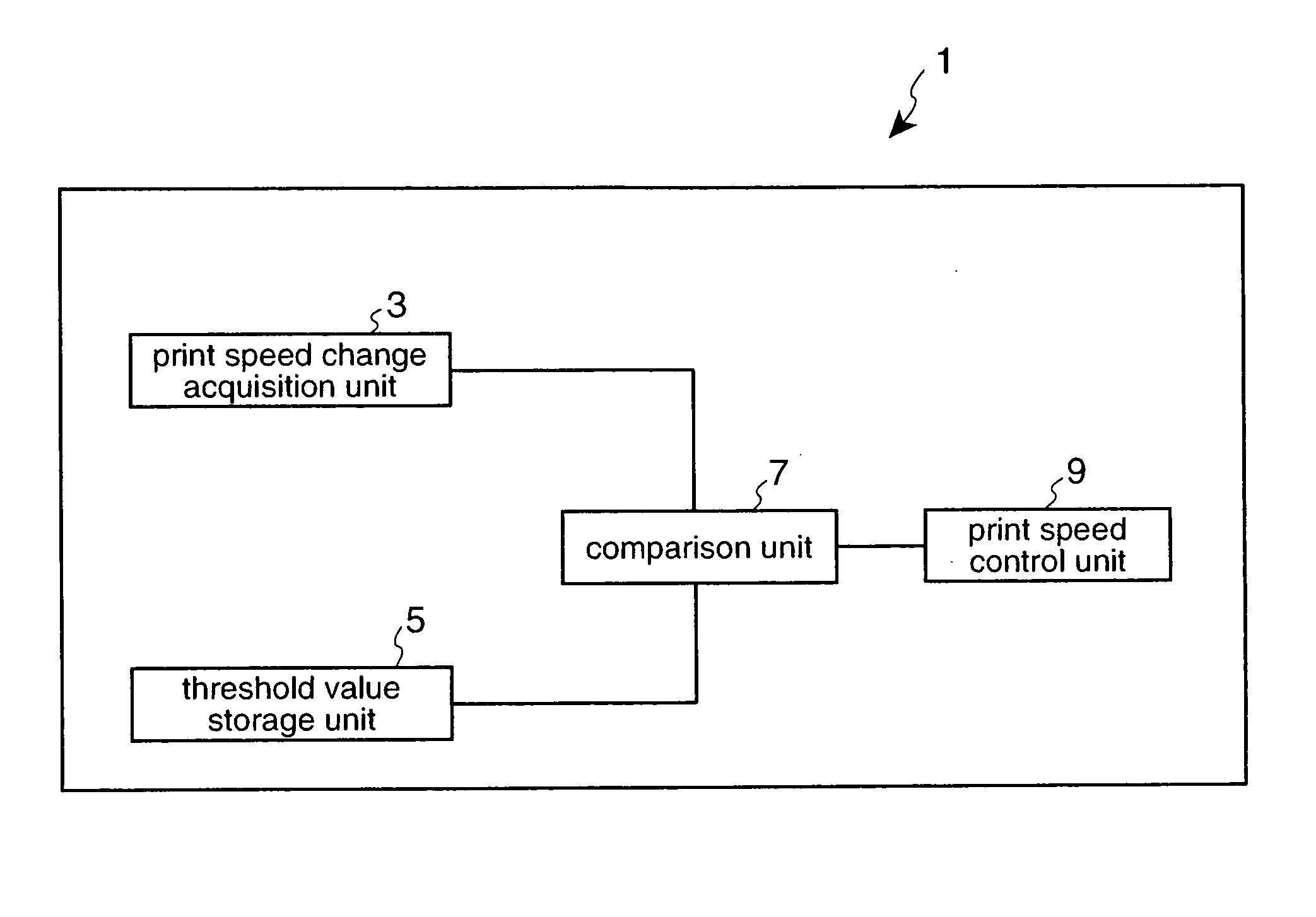
[0034] Referring to the drawings and in particular to FIGS. 4, 5 and 7 the thermal printer 1 of the present invention comprises: a paper feed mechanism (31, 32 and 33) as shown in FIG. 5; a print speed control unit 9(FIG 4), comparison unit 7(FIG 4), a threshold value storage unit 5 (FIG. 4) and a print speed acquisition unit 3 (FIG. 4). The print speed control unit 9, the comparison unit 7 and the print speed acquisition unit 3 are the functional equivalents to hardware in FIG. 5 including the control device 11 (CPU) and the print speed calculation circuit 13 which operate in conjunction with ROM 17 and RAM 19 to calculate and control the print speed of the paper feed mechanism as explained hereafter in greater detail. The print speed corresponds to the paper feed rate during printing based on the print speed control factors.

[0035] The comparison unit 7 of FIG. 4 will hereafter be referred to as an evaluation unit for determining if the change in print speed exceeds a predetermine...


PUM


Abstract

A thermal printer 1 and control method for controlling print speed to prevent variation in printing pitch due to frequent slight changes in the print speed following a significant change in print speed. The print speed, which is the speed at which the print medium i.e., paper is conveyed when printing, is controlled based on known print speed control factors. The thermal printer comprises a paper feed mechanism for conveying the print medium at a controlled print speed passed a thermal print head, a print speed control unit 9 for controlling the print speed of the paper feed mechanism based on the print speed control factors, a print speed change acquisition unit 3 for determining the change in the print speed over a predetermined time, and a comparison unit 7 for determining if the change in print speed exceeds a predetermined threshold value. The print speed control unit 9 limits change in the print speed based on the print speed control factors for a predetermined time after the comparison unit 7 determines that the change in print speed exceeds the threshold value.

Description

BACKGROUND OF THE INVENTION [0001] 1. Field of Technology [0002] The present invention relates to a thermal printer for printing to a print medium at a controlled print medium speed relative to a print head, a thermal printer control method, and a printing system. [0003] 2. Description of Related Art [0004] Thermal printers hold a print medium such as thermal paper between the thermal print head and a platen roller and advance the paper by rotating the platen roller. The thermal print head has heating elements (dots) arrayed in a line (one dot line) across the width of the paper, and applies current to selected dots in this dot line to produce heat and cause the thermal paper to change color. The thermal printer prints by energizing the thermal print head while advancing the thermal paper. Torque for rotating the platen roller is transferred from a rotational drive source such as a stepping motor through a transfer mechanism (a gear train) to the platen roller. [0005] The printing s...

Claims


Application Information

Patent Timeline
Patent Type & Authority Applications(United States)
IPC IPC(8): B41J2/00
CPCB41J11/42B41J2/355
Inventor KOYABU, AKIRANAKAJIMA, SATOSHITAKIGUCHI, YUJI
Owner SEIKO EPSON CORP
Why Eureka
Try Eureka