
Receiver unit and method for receiving an analogue received signal

a technology of receiving unit and receiving signal, which is applied in the direction of transmission, transmission monitoring, electrical apparatus, etc., can solve the problems of high power consumption and chip surface required for several analog-digital converters, and achieve the effect of reducing chip surface, cost and power consumption

Inactive Publication Date: 2007-01-25
ROBERT BOSCH GMBH
View PDF4 Cites 8 Cited by
  • Summary
  • Abstract
  • Description
  • Claims
  • Application Information

AI Technical Summary

Benefits of technology

[0004] An objective of the present invention therefore is to provide an improved receiver unit with which it is possible to reduce the chip surface, costs and power consumption for the analog-digital converters.
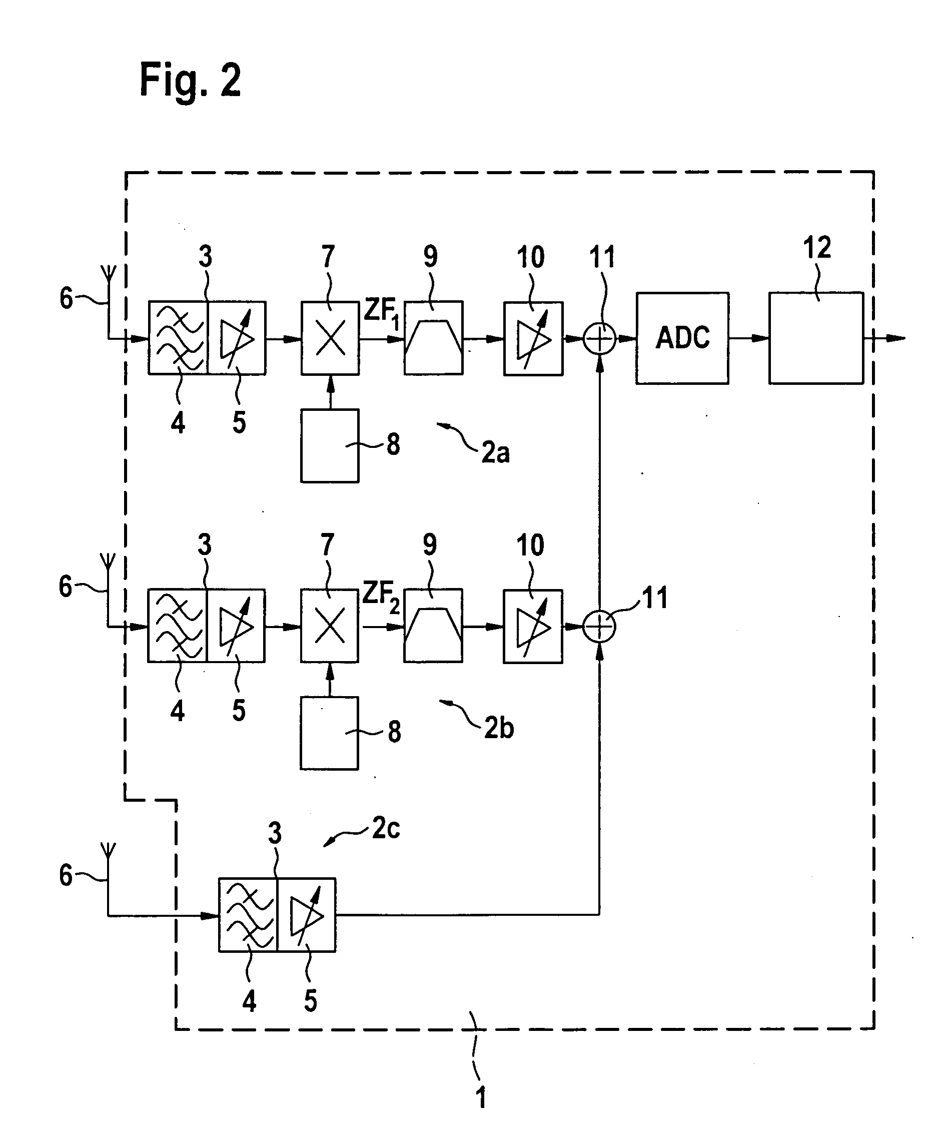
[0006] Thus, it is provided to use a common analog-digital converter for the several signal receivers, the individual analog received signals being added up beforehand and the digital added-up common received signal being separated again later in the digital part. This has the advantage of requiring only a single analog-digital converter. The separation is readily possible in the digital part, particularly if the analog received signals having different receiving frequencies are added up. These may then be readily filtered out by the signal processing unit using channel filtering.
[0008] For this purpose, at least one signal receiver should be configured for mixing an analog received signal to intermediate frequency and at least one other signal receiver should be configured for receiving and filtering one defined receiving frequency band and adding this receiving frequency band to the intermediate frequency signal. In this manner, it is easy to separate the intermediate frequency signal in the digital signal receiver from the rest of the receiving frequency band. On account of the digitalization of a defined receiving frequency band, it is easy to continue to monitor the range of receivable radio broadcast stations and to extract data from this receiving frequency band.
[0009] It is furthermore advantageous if the several signal receivers are provided for the simultaneous reception of analog received signals on different channels and / or according to different transmission standards. This makes it possible to receive different receiving channels and different standards and to process these further in the digital part of the receiver unit.

Problems solved by technology

The chip surface and power consumption currently required for the several analog-digital converter, however, is too high.

Method used


Image

  • Receiver unit and method for receiving an analogue received signal
  • Receiver unit and method for receiving an analogue received signal
  • Receiver unit and method for receiving an analogue received signal

Examples


Embodiment Construction

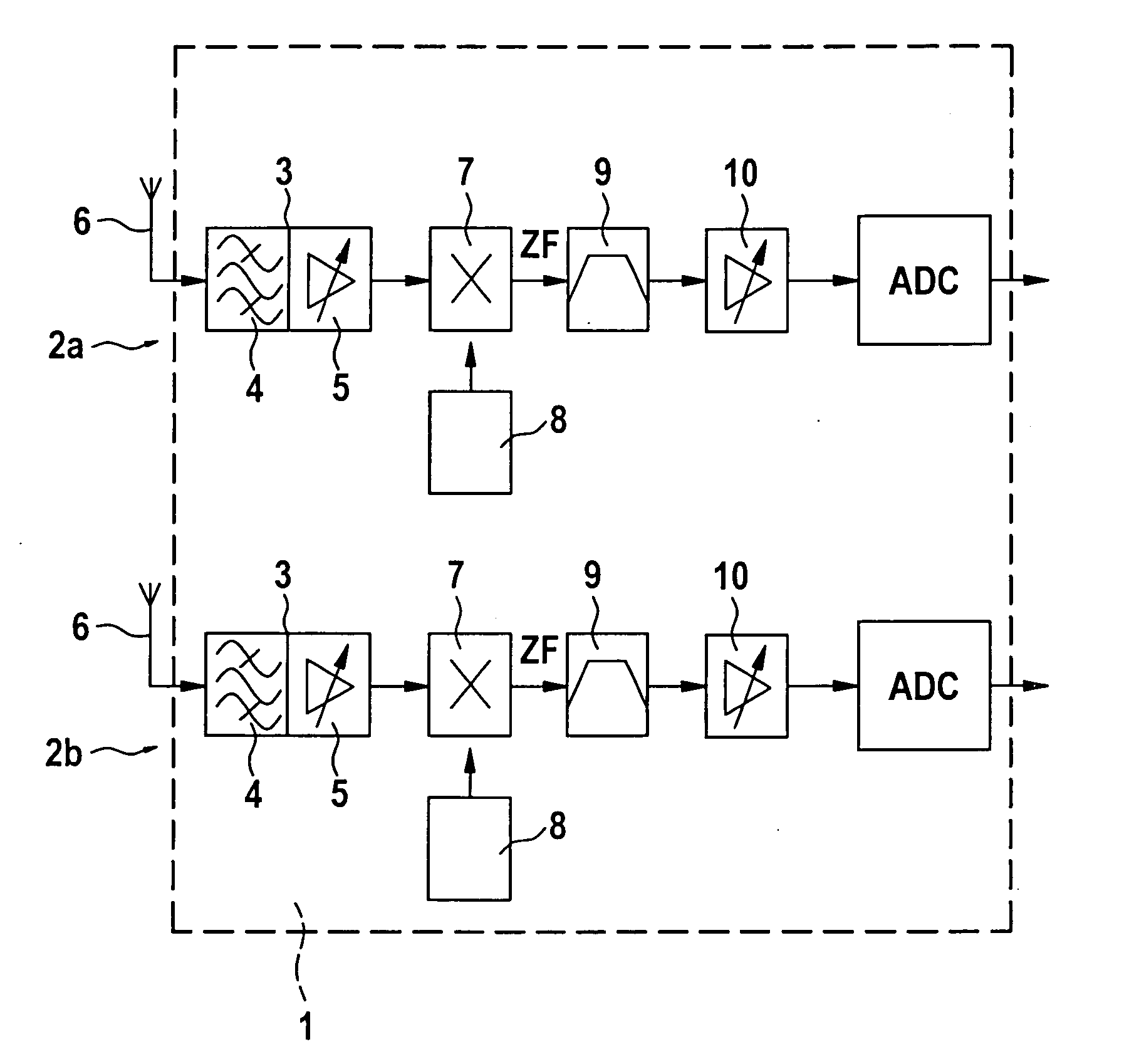
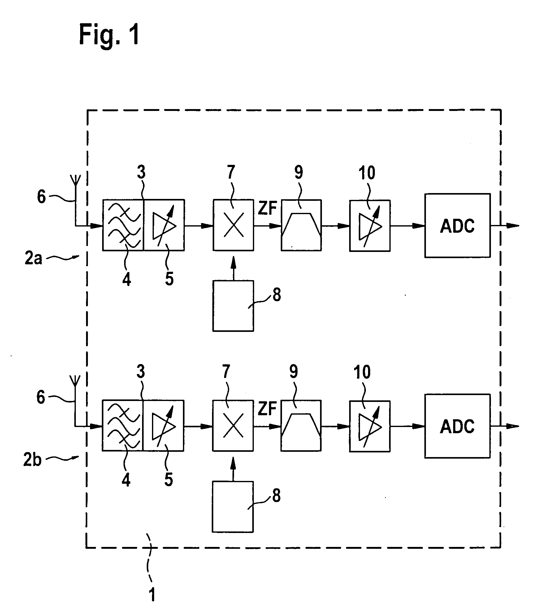
[0017]FIG. 1 shows a block diagram of a conventional receiver unit for the simultaneous reception of several analog receiver signals on the same or different receiving channels and / or according to the same transmission standards. Every signal receiver 2 has a prestage 3 having a band-pass filter 4 and a preamplifier 5. The input of prestage 3 is connected to an antenna 6 and the output of prestage 3 is in each instance connected to a mixer 7. Mixer 7 is triggered by an oscillator 8 so as to mix the analog received signal to an intermediate frequency ZF. The intermediate frequency signal ZF is filtered in an intermediate frequency filter 9 and is subsequently amplified using an amplifier 10.

[0018] Every signal receiver 2a has an analog-digital converter ADC for converting the amplified analog intermediate frequency signal into a digital received signal and subsequently process it further digitally using a signal processing unit (not shown).

[0019]FIG. 2 shows a block diagram of a re...


PUM


Abstract

A receiver unit, having at least two signal receivers for analog received signals, an analog-digital converter for converting the analog received signals into digital received signals, and having a signal processing unit for the digital received signals, has at least at least one adder at the output of the signal receivers for adding the analog received signals, the adder being connected with its output to the input of a common analog-digital converter and the digital signal processing unit being configured to separate the added received signals.

Description

FIELD OF THE INVENTION [0001] The present invention relates to a receiver unit having at least two signal receivers for analog received signals according to digital or analog standard, an analog-digital converter for converting the analog received signals into digital received signals and a signal processing unit for the digital received signals. The present invention additionally relates to a method for receiving analog received signals, particularly radio broadcast signals, using a receiver unit of this kind. BACKGROUND INFORMATION [0002] Conventional radio broadcast receivers for receiving amplitude-modulated (AM) and frequency-modulated (FM) received signals often have more than one signal receiver so as to receive, for example, an audio signal on a first channel and at the same time data on a second channel. The data may be transmitted, for example, in accordance with the Radio Data Standard (RDS) or in the Traffic Message Channel (TMC). The several signal receivers may also be...

Claims


Application Information

Patent Timeline
IPC IPC(8): H04B17/02H04B1/28H04B1/40H04B17/40
CPCH04B1/0003H04B1/0007H04B1/406H04B1/006H04B1/28H04B1/005
Inventor PASSOKE, JENS
Owner ROBERT BOSCH GMBH
Learn More