Method and system for operating a multi-stage combustor
a gas turbine engine and multi-stage technology, applied in the ignition of the turbine/propulsion engine, instruments, lighting and heating apparatus, etc., can solve the problem of less preferred methods and achieve the effect of better control of emissions
- Summary
- Abstract
- Description
- Claims
- Application Information
AI Technical Summary
Benefits of technology
Problems solved by technology
Method used
Image
Examples
Embodiment Construction
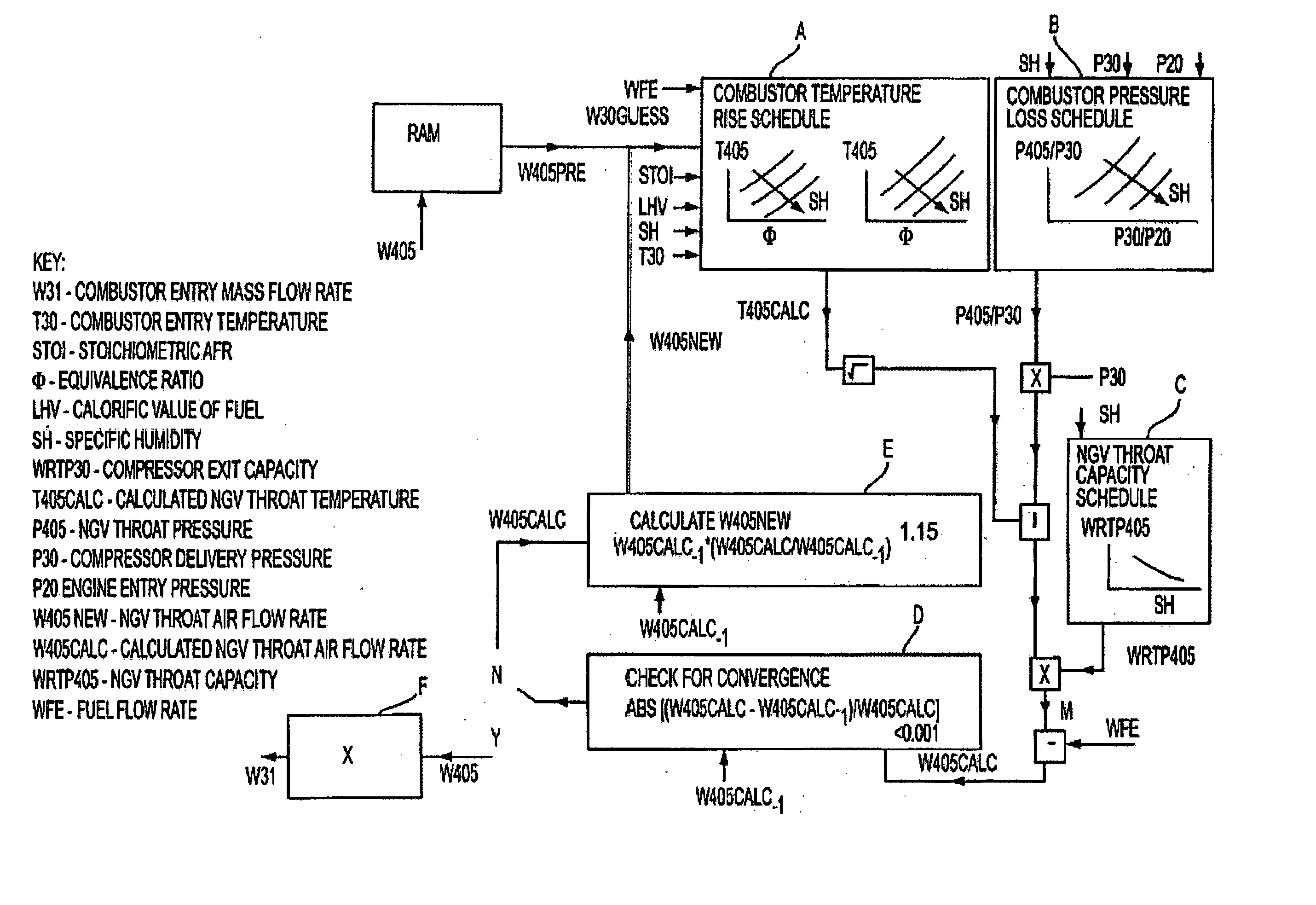
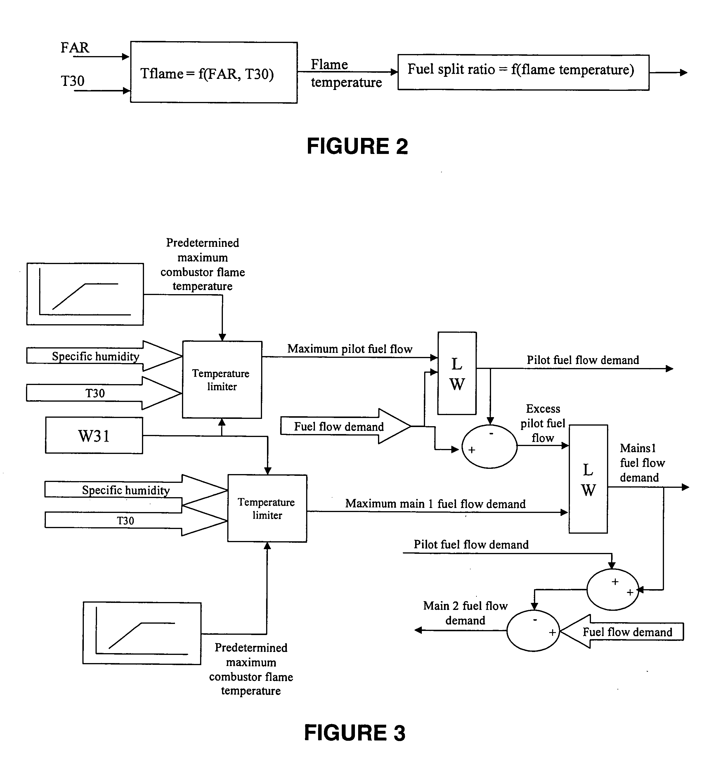
[0051] A typical gas turbine engine comprises, in axial flow series, a low pressure (LP) compressor, a high pressure (HP) compressor, a combustor, an HP turbine, an LP turbine, and an exhaust. The LP and HP turbines drive the corresponding compressors through concentric shafts within the engine, each assembly of a turbine and a shaft joined together by shaft being termed a “spool”. Single spool and triple spool gas turbine engines are also used. Nozzle guide vanes (NGVs), situated immediately in front of the HP turbine, receive the hot gases released by the combustor.
[0052] The combustor of a gas turbine engine can take many forms. U.S. Pat. No. 5,743,079 describes a combustor for an industrial gas turbine which has nine separate combustion chambers disposed within separate casings of generally cylindrical form. The casings project generally radially outwards of the rest of the engine and are equiangularly spaced around the engines's longitudinal axis. Each combustion chamber has a...
PUM
 Abstract
Description
Claims
Application Information
 - R&D
- Intellectual Property
- Life Sciences
- Materials
- Tech Scout
- Unparalleled Data Quality
- Higher Quality Content
- 60% Fewer Hallucinations
Browse by: Latest US Patents, China's latest patents, Technical Efficacy Thesaurus, Application Domain, Technology Topic, Popular Technical Reports.
© 2025 PatSnap. All rights reserved.Legal|Privacy policy|Modern Slavery Act Transparency Statement|Sitemap|About US| Contact US: help@patsnap.com


