Spinning device for producing a yarn by means of a circulating air flow

a spinning device and air flow technology, applied in yarn, open-end spinning machines, textiles and papermaking, etc., can solve the problems of relatively low maintenance cost, relatively high maintenance cost, and traces of wear and tear on the device, and achieve the effect of prolonging the service life of the mechanism

Inactive Publication Date: 2007-02-01
SAURER GERMANY GMBH & CO KG
View PDF6 Cites 11 Cited by
  • Summary
  • Abstract
  • Description
  • Claims
  • Application Information

AI Technical Summary

Benefits of technology

[0008] Proceeding from spinning devices of the type mentioned at the outset, the invention is based on the object of improving air spinning devices with a spinning cone which is stationary during the spinning process by significantly extending the service life of the mechanisms, in particular the service life of the highly stressed spinning cone.
[0011] For example, the configuration of an air spinning device according to the invention with a spinning cone which can be adjusted with regard to its installation angle position, has the advantage that during the usage time of the spinning device, the position of the spinning cone with respect to its bearing arrangement can be easily changed repeatedly and point-wise over-stressing of the spinning cone material, which would lead to premature wear of the spinning cone, can thus be prevented. In other words, by repeatedly rotating the spinning cone about its longitudinal axis, preferably by one or more angular degree(s), for example randomly in the course of a spinning interruption, at each spinning interruption or else at periodic intervals, the impact points of the air flows introduced through the blast nozzles and impacting on the spinning cone in the region of the head, which are primarily responsible for the increased wear, can be gradually distributed over the entire periphery of the spinning cone.
[0012] In this manner, particularly high material stressing of individual points of the spinning cone can be successfully prevented and it can be ensured that in the course of time, the entire periphery of the spinning cone head is stressed virtually uniformly.
[0013] The spinning cone is advantageously rotatably mounted via a clearance fit, for example, in the rear bearing housing of the outer housing of the air spinning device and, is fixed, if necessary to be easily releasable, by a permanent magnet arrangement in the desired installation angle position on the outer housing. Such a simple and robust construction ensures, on the one hand, reliable fixing of the spinning cone during the spinning process and, on the other hand, makes it possible for the operating staff to adjust the installation angle position of the spinning cone without problems, preferably with reference to an event or time, but also randomly.
[0014] The adjustment of the installation angle position of the spinning cone, which is preferably only a few angular degrees, in each case, takes place in an advantageous embodiment, by hand, by the operating staff. Such a manually adjustable spinning cone is economical to manufacture, on the one hand, and easy for the operating staff to operate, on the other hand.
[0015] In a preferred embodiment, the spinning cone also has a marking, from which the respective installation angle position of the spinning cone can easily be recognized in the bearing arrangement. It can easily be ascertained, by means of a marking of this type, for example by means of a simple comparison of the installation angle position of the relevant spinning cone with the installation angle position of adjacent spinning cones, whether the relevant spinning cone has already been rotated into its new angle position with regard to rotation or whether it has so far been neglected to rotate this spinning cone into the new position. In other words, a marking of this type substantially facilitates uniform adjustment of the installation angle positions of the spinning cones.

Problems solved by technology

The drawback in this known air spinning device, however, is that the device is relatively maintenance-intensive due to its rotatably mounted, driven spinning spindle.
Air spinning devices according to German Patent Publication DE 199 26 492 A1 are distinguished above all by a relatively simple design construction and are relatively low in maintenance.
However, it has been shown that in the case of air spinning devices of this type with a fixed spinning cone, even though it is made of a very wear-resistant material, preferably an industrial ceramics material, there is the risk of traces of wear occurring over time in certain areas of the head of the spinning cone and these have negative effects on the functioning capacity of the device.

Method used


Image

  • Spinning device for producing a yarn by means of a circulating air flow
  • Spinning device for producing a yarn by means of a circulating air flow
  • Spinning device for producing a yarn by means of a circulating air flow

Examples


Embodiment Construction

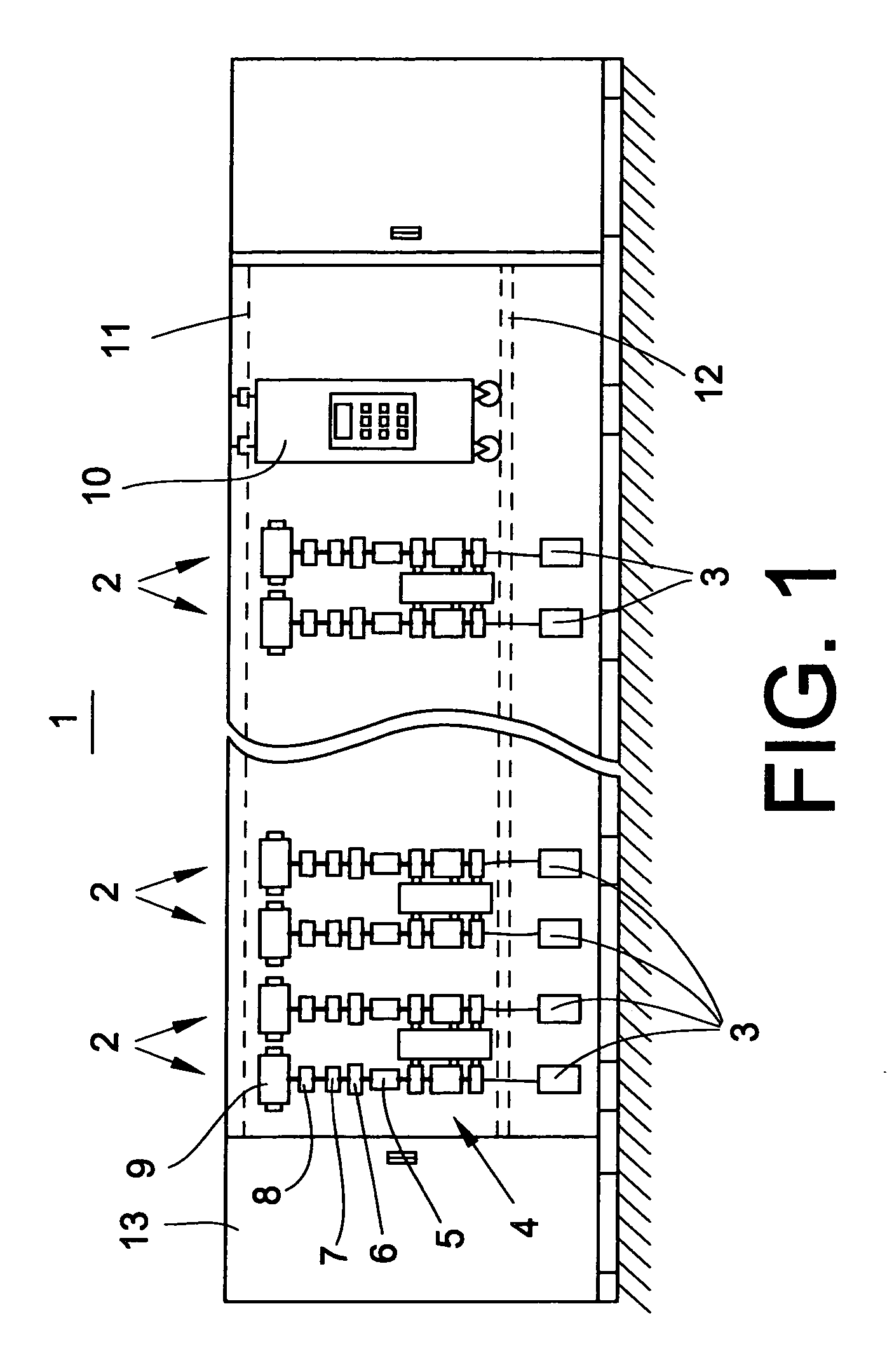
[0021] The air spinning machine 1 shown in a front view in FIG. 1 has a plurality of workstations 2 arranged next to one another in a row and a drive unit 13, at at least one end of the air spinning machine 1.

[0022] Each of the workstations or spinning stations 2 of the textile machine 1 has a fiber band source, for example a spinning can 3, a drafting arrangement 4, an air spinning device 5, a yarn draw-off mechanism 6, a yarn clearer 7 and a yarn traversing mechanism 8. The yarn traversing mechanism 8 ensures that the yarn finished in the air spinning device 5 is wound in crossing layers onto a take-up bobbin 9. The cross-wound bobbin 9, as usual, is held in a creel (not shown), and is rotated by a bobbin drive (also not shown). As also indicated in FIG. 1, the spinning stations 2 of the textile machine 1 are supplied by an automatically operating traveller 10, which, guided on rails 11, 12, can be moved along the spinning stations 2.

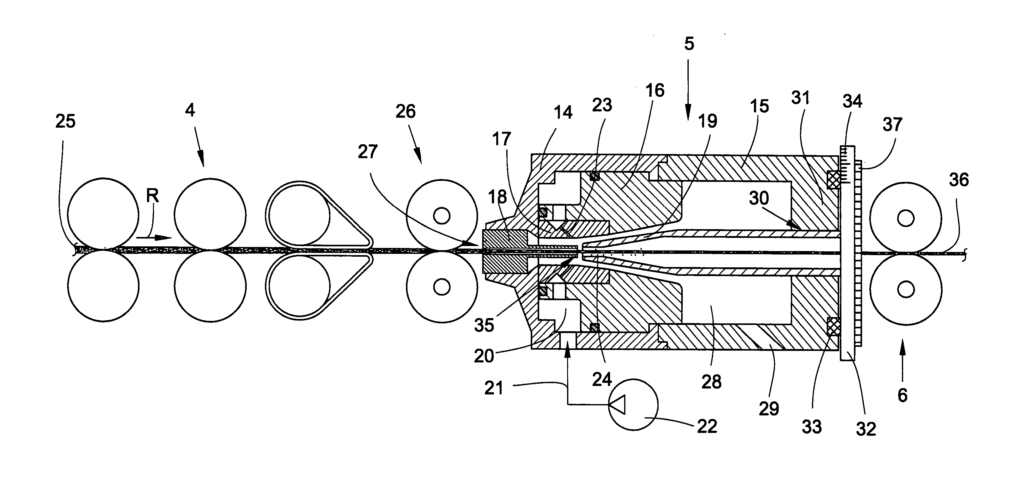
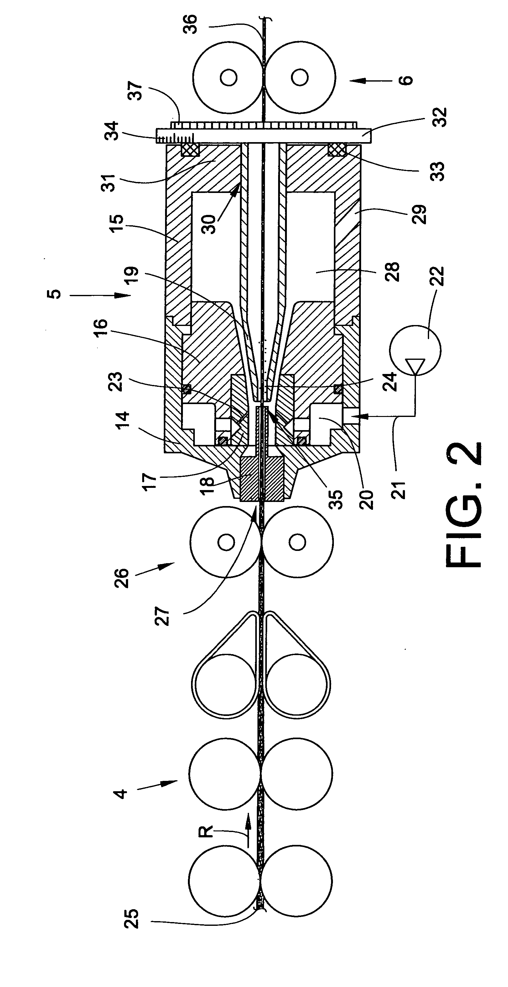
[0023]FIG. 2 shows the air spinning device 5,...


PUM

PropertyMeasurementUnit
angleaaaaaaaaaa
installation angleaaaaaaaaaa
pressureaaaaaaaaaa

Abstract

A spinning device for producing a yarn by a circulating air flow, comprising a hollow spinning cone arranged in a spinning housing and rotatably mounted about a central longitudinal axis and a nozzle block which can be loaded with compressed air to generate the circulating air flow. The spinning cone (19) is mounted via a bearing arrangement (30) in the rear housing part (15) such that the installation angle position of the spinning cone (19) can be adjusted selectively inside the air spinning device (5).

Description

CROSS-REFERENCES TO RELATED APPLICATIONS [0001] This application claims the benefit of German patent application 10 2005 035 049.6 filed Jul. 27, 2005, herein incorporated by reference. BACKGROUND OF THE INVENTION [0002] The invention relates to a spinning device for producing a yarn by means of a circulating air flow and, more particularly, comprising a hollow spinning cone arranged in a spinning housing and rotatably mounted about a central longitudinal axis, and a nozzle block which can be loaded with compressed air to generate the circulating air flow. [0003] Air spinning devices for producing textile yarns are known in various embodiments and described in the patent literature. [0004] German Patent Publication DE 40 36 119 C2 describes an air spinning device, for example, in which a fiber yarn drawn in an upstream drafting arrangement is introduced through a nozzle block into an air spinning device and arrives via a fiber band guide, which also acts as a twist stop in the inlet...

Claims


Application Information

Patent Timeline
Patent Type & Authority Applications(United States)
IPC IPC(8): D01H5/28D01H1/115
CPCD01H4/02D01H1/115
Inventor WEIDE, THOMAS
Owner SAURER GERMANY GMBH & CO KG
Why Eureka
Try Eureka