Focused droplet nebulizer for evaporative light scattering detector

a droplet nebulizer and detector technology, applied in the field of evaporative light scattering detection, can solve the problems of incomplete solvent evaporation, large background noise, incomplete evaporation and erratic measurement performan

Inactive Publication Date: 2007-02-01
UNIVERSITY OF MISSOURI
View PDF11 Cites 25 Cited by
  • Summary
  • Abstract
  • Description
  • Claims
  • Application Information

AI Technical Summary

Benefits of technology

[0007] A focused droplet nebulizer of the invention produces substantially uniform droplets of a predetermined size. Droplets are pushed out through a small outlet orifice by the contraction of a chamber. The droplets can be carried on a substantially non-divergent path in a drift tube. A piezo membrane micro pump acts in response to an electrical control signal to force a droplet out of the outlet orifice. The nebulizer can operate at frequencies permitting a stream of individual droplets of the predetermined size to be sent along the substantially non-divergent path in the drift tube of a preferred embodiment ELSD device.

Problems solved by technology

One problem with conventional nebulizers is that complete solvent evaporation does not occur in the drift tube.
The expanding trajectory and variable sizes of the droplets produced by conventional nebulizers contributes to the incomplete evaporation and erratic measurement performance.
This droplet scattering creates a large level of background noise.
The small droplets result in analyte particles that are too small to contribute to the detection signal.
However, the small droplets increase solvent vapor pressure in the drift tube.
However, the rate of incomplete droplet vaporization and their distribution (size and number) tends to change randomly with time.
This causes uncertainty in the analyte signal, in addition to the substantial level of background noise.
Excluding larger droplets produced by a conventional nebulizer proves difficult in practice because the nature of the droplet distribution depends strongly on three factors: mobile phase composition, mobile phase flow rate and carrier gas flow rate.
The dependence is highly interactive, which makes the spray hard to control and difficult to model.
These undesirable nebulizer characteristics place extraordinary demands on the structural design of ELSD units, making their design very complicated and highly empirical.

Method used


Image

  • Focused droplet nebulizer for evaporative light scattering detector
  • Focused droplet nebulizer for evaporative light scattering detector
  • Focused droplet nebulizer for evaporative light scattering detector

Examples


Embodiment Construction

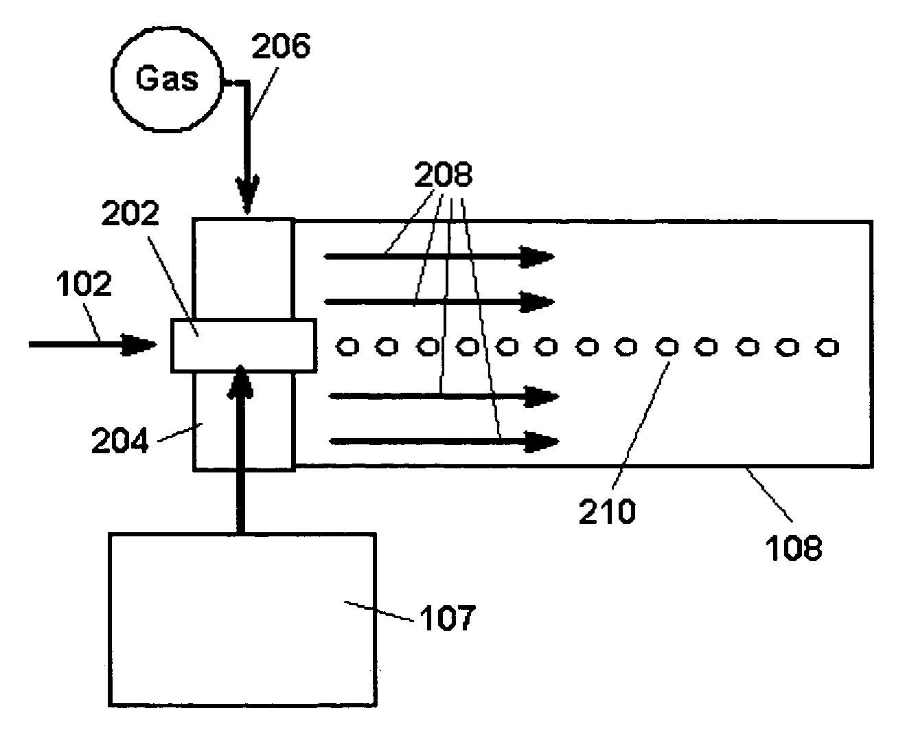
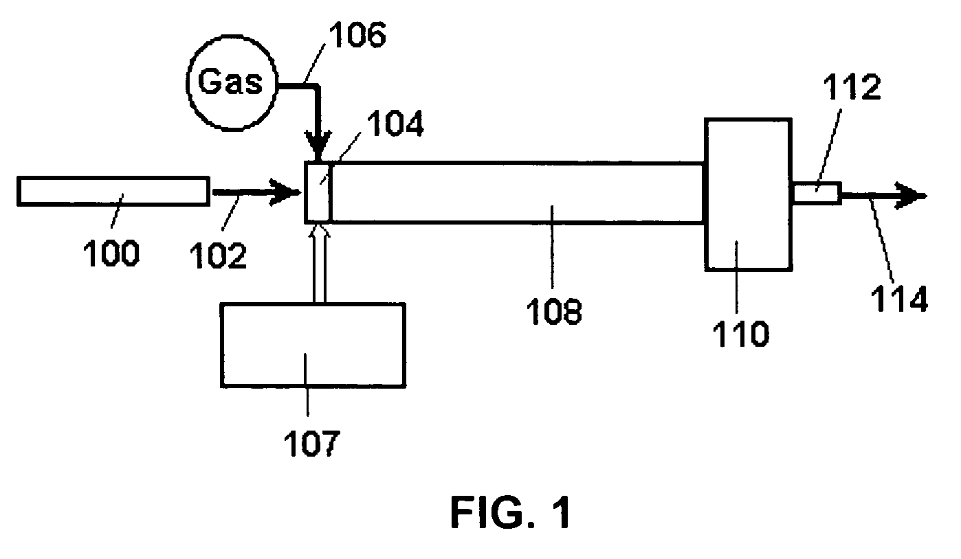
[0015] The problems inherent with the use of a conventional nebulizer ultimately limit performance in evaporative light scattering detectors (ELSDs). Size, complexity, and cost are also adversely affected by the nebulizer. The invention provides a focused droplet nebulizer. A nebulizer of the invention produces substantially uniform sized droplets. Preferred embodiment nebulizers also provide a precisely controlled droplet production rate and deliver droplets along a focused path. An ELSD of the invention uses a focused droplet nebulizer to reduce background noise and improve the state of ELSD detection.

[0016] A preferred embodiment focused droplet nebulizer includes a piezo membrane micro pump. The piezo membrane micro pump has an inlet with a check valve that allows liquid to flow one way into the pump. When the piezo membrane expands, liquid is drawn into the pump and when the piezo membrane contracts, liquid is forced out a tiny outlet orifice. This creates a small single dropl...


PUM


Abstract

A focused droplet nebulizer of the invention produces substantially uniform droplets of a predetermined size. Droplets are pushed out through a small outlet orifice by the contraction of a chamber. The droplets can be carried on a substantially non-divergent path in a drift tube. A piezo membrane micro pump acts in response to an electrical control signal to force a droplet out of the outlet orifice. The nebulizer can operate at frequencies permitting a stream of individual droplets of the predetermined size to be sent along the substantially non-divergent path in the drift tube in a preferred embodiment ELSD device.

Description

FIELD OF THE INVENTION [0001] The invention is in the field of evaporative light scattering detection. BACKGROUND [0002] Evaporative light scattering detectors (ELSDs) are used routinely for Liquid Chromatography (LC) analysis. In an ELSD, a liquid sample is converted to droplets by a nebulizer. As the droplets traverse a drift tube, the solvent portion of the droplets evaporates, leaving less volatile analyte. The sample passes to a detection cell, where light scattering of the sample is measured. ELSDs can be used for analyzing a wide variety of samples. [0003] The present inventors identify the nebulizer as a limit on the effectiveness of the detection capabilities of ELSDs. One problem with conventional nebulizers is that complete solvent evaporation does not occur in the drift tube. The expanding trajectory and variable sizes of the droplets produced by conventional nebulizers contributes to the incomplete evaporation and erratic measurement performance. Droplets enter the dete...

Claims


Application Information

Patent Timeline
Patent Type & Authority Applications(United States)
IPC IPC(8): A61M11/00
CPCA61M11/005G01N30/74G01N30/84A61M16/1095G01N2030/847G01N21/47A61M11/001A61M11/00
Inventor LARSEN, DAVID W.XU, ZHI
Owner UNIVERSITY OF MISSOURI
Why Eureka
Try Eureka