Apparatus for cooling electronic components

Inactive Publication Date: 2007-02-01
BEHR IND
View PDF9 Cites 13 Cited by
  • Summary
  • Abstract
  • Description
  • Claims
  • Application Information

AI Technical Summary

Benefits of technology

[0005] It is therefore one object of the present invention to provide an improved apparatus for cooling electronic com

Problems solved by technology

Production of the known cooling device entails relatively high costs, since the cavity is produced by machining (milling) the base plate and is sealed by means of a cover plate which is screwed to the base plate.
In addition, depending on the arrangement and respective power loss of the electronic components, a non-uniform introduction of heat may result for the base plate, which may result in d

Method used


Image

  • Apparatus for cooling electronic components
  • Apparatus for cooling electronic components
  • Apparatus for cooling electronic components

Examples


Example

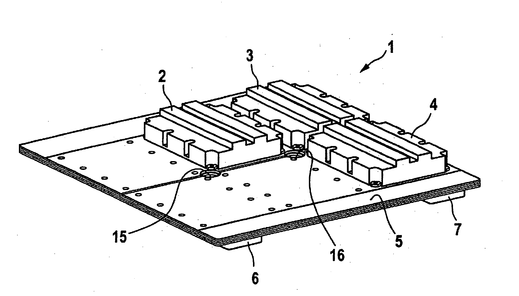
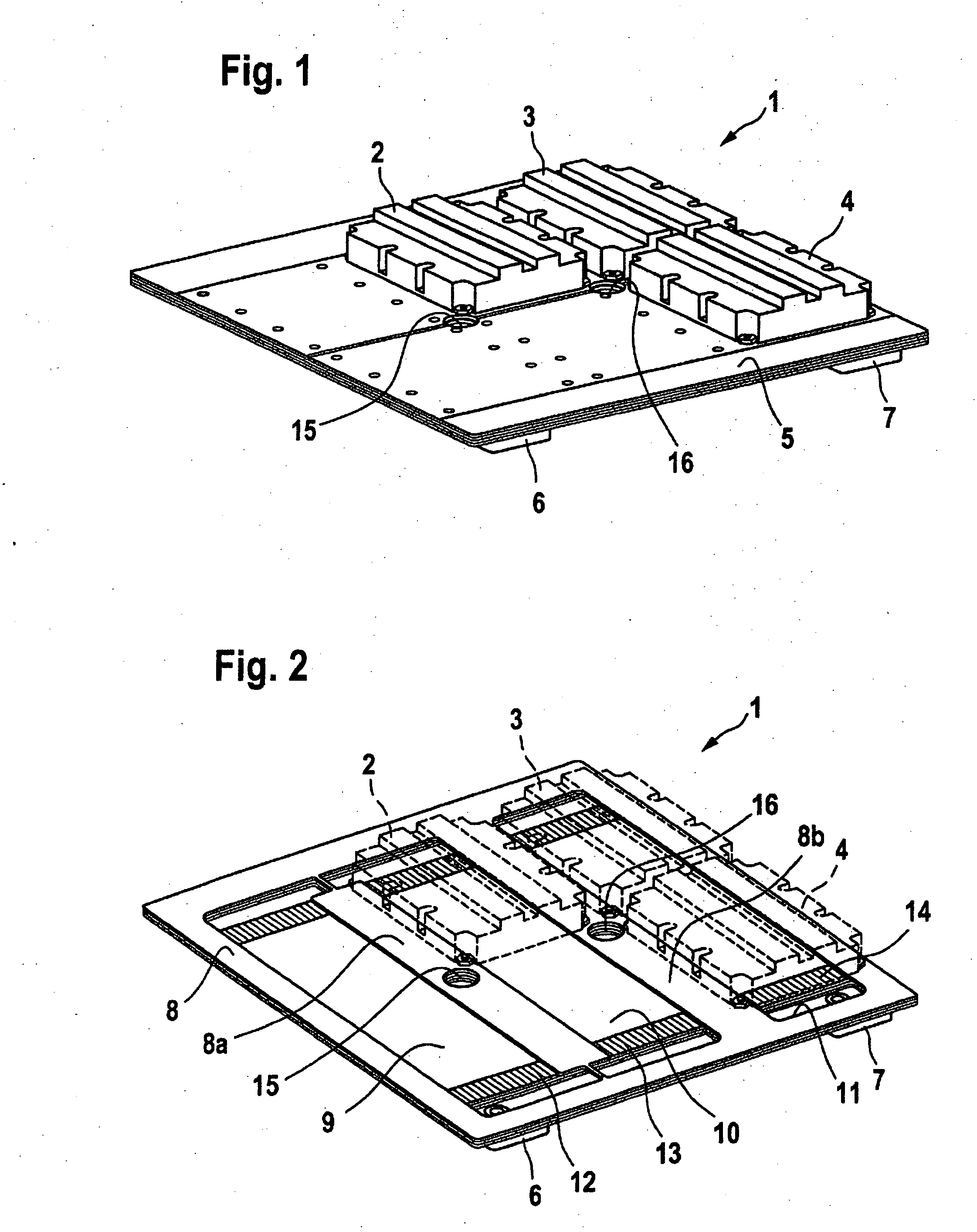
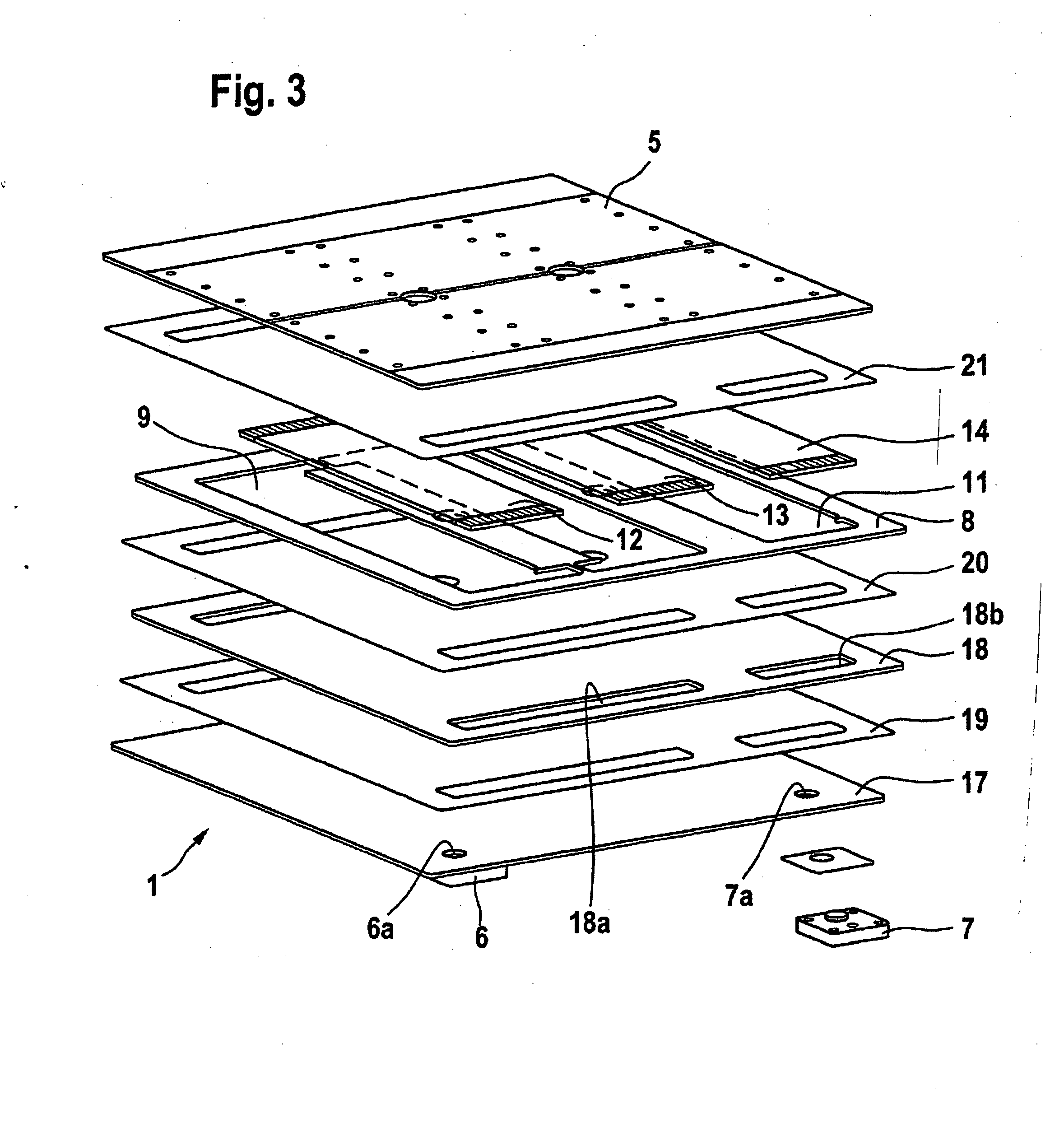
[0015] The invention provides for at least one plate-like frame element having cutouts arranged between the plate-like parts, the cutouts forming sections of a flow duct. The cutouts are thus connected to one another on the coolant side, it being possible for the cutouts to be connected in series and / or in parallel with one another. In principle, the cutouts have any desired shape and are matched, in terms of shape and arrangement, to the electronic components that are arranged on the cooling apparatus. Turbulence inserts that are positioned through the cutouts and improve the heat transfer to the coolant can optionally and advantageously be arranged in the cutouts. The plate-like frame element and the plate-like parts are preferably connected to one another by means of brazing or soldering, whereby plate-like carriers for brazing material are preferably used for this purpose. The advantageous feature of this design is the simple structure which is achieved by stacking and brazing / s...


PUM


Abstract

An apparatus (1) for cooling electronic components (2, 3, 4) comprises laminated plate-like parts that form a flow duct through which a liquid coolant can flow. At least one plate-like frame element (8) having cutouts (9, 10, 11) is arranged between the plate-like parts, wherein the cutouts (9, 10, 11) form sections of a coolant flow duct for selectively cooling electronic components mounted on mounting areas on one or more surfaces of the apparatus.

Description

CROSS-REFERENCE TO RELATED PATENT APPLICATIONS [0001] The right of foreign priority is claimed under 35 U.S.C. § 119(a) based on Federal Republic of Germany Application No. 10 2005 034 998.6, filed Jul. 27, 2005, the entire contents of which, including the specification, drawings, claims and abstract, are incorporated herein by reference. BACKGROUND OF THE INVENTION [0002] The invention relates to an apparatus for cooling electronic components, of the type comprising plate-like parts which form a flow duct through which a liquid coolant can flow. [0003] A known cooling device of this type is disclosed in commonly assigned DE 41 31 739 A1, for use in cooling electrical components. This device essentially comprises two plate-like parts, a base plate and a cover plate, which enclose a cavity through which a liquid coolant can flow. In order to improve the heat transfer, a turbulence insert is arranged in the cavity that acts as a flow duct. The electrical components are arranged on the...

Claims


Application Information

Patent Timeline
IPC IPC(8): H05K7/20
CPCH01L23/473H01L2924/0002H01L2924/00
Inventor FLESCH, MARKUSKLENK, ANDREASSIEBRECHT, THOMAS
Owner BEHR IND
Why Eureka
Try Eureka