Combined pneumatic cylinder and corresponding control method

Inactive Publication Date: 2007-02-01
KNORR-BREMSE SYST FUER NUTZFAHRZEUGE GMBH
View PDF6 Cites 2 Cited by
  • Summary
  • Abstract
  • Description
  • Claims
  • Application Information

AI Technical Summary

Benefits of technology

[0007] In accordance with the present invention, a combined pneumatic cylinder for a vehicle brake is provided which has the following features: a brake cylinder housing, in which a piston which is arranged on a piston rod is guided displaceably and which is divided by the piston into two pressure spaces which each have a compressed air connection, one end of the piston rod penetrating the brake cylinder housing to the outside, and a spring for realizing the parking brake function also being arranged directly in one of the two pressure spaces which is designed for carrying out service brake operations by way of a pressure increase, with the result that the service brake function and the parking brake function can be realized with only two pressure spaces and the spring.
[0008] With regard to the method for controlling a combined pneumatic cylinder of this type, the invention is distinguished by the fact that, in parking brake operations, the pressure in the first pressure space without a spring is reduced, with

Problems solved by technology

They are, therefore, often of relatively

Method used


Image

  • Combined pneumatic cylinder and corresponding control method
  • Combined pneumatic cylinder and corresponding control method
  • Combined pneumatic cylinder and corresponding control method

Examples


Example

DETAILED DESCRIPTION OF THE DRAWINGS

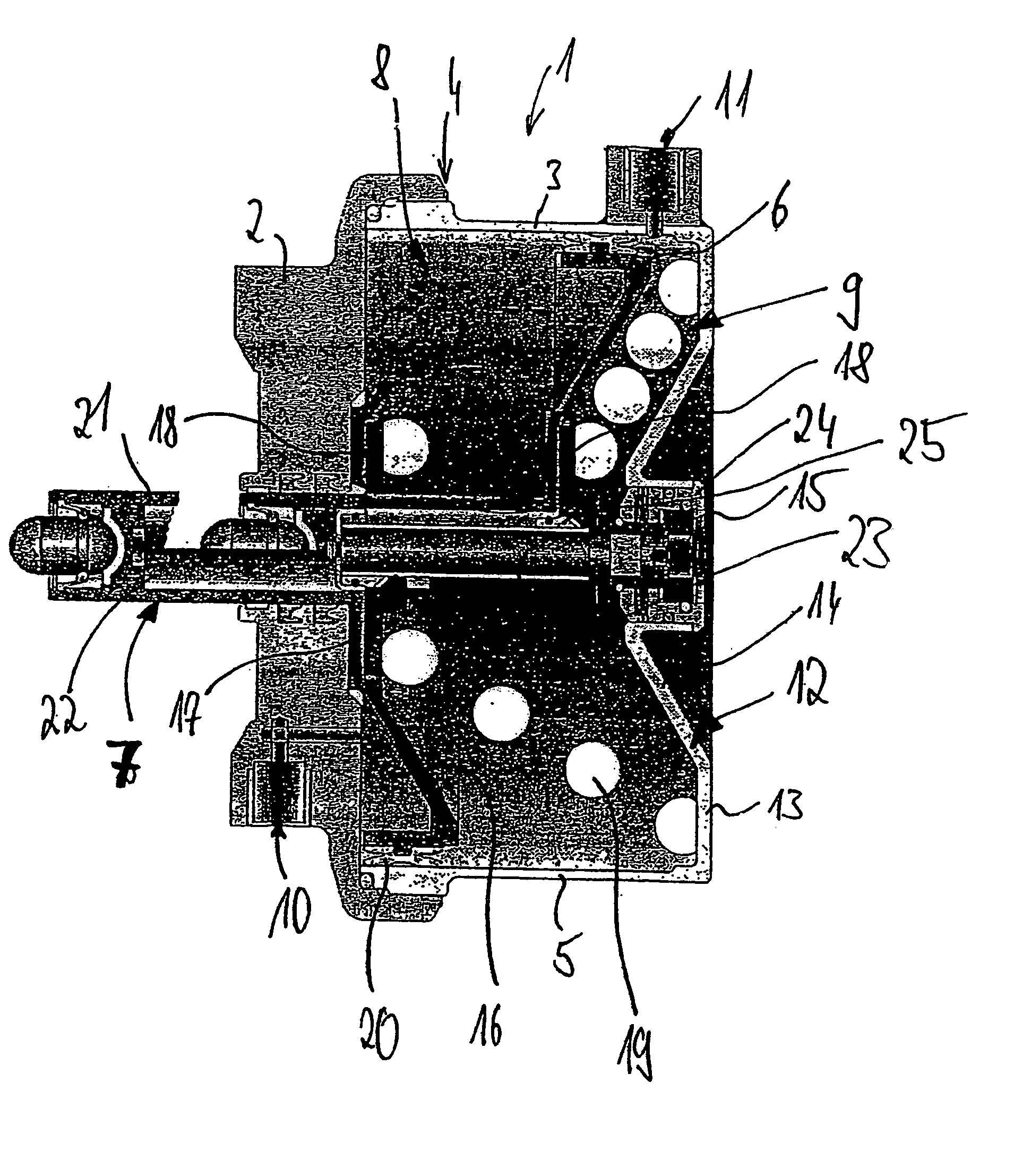
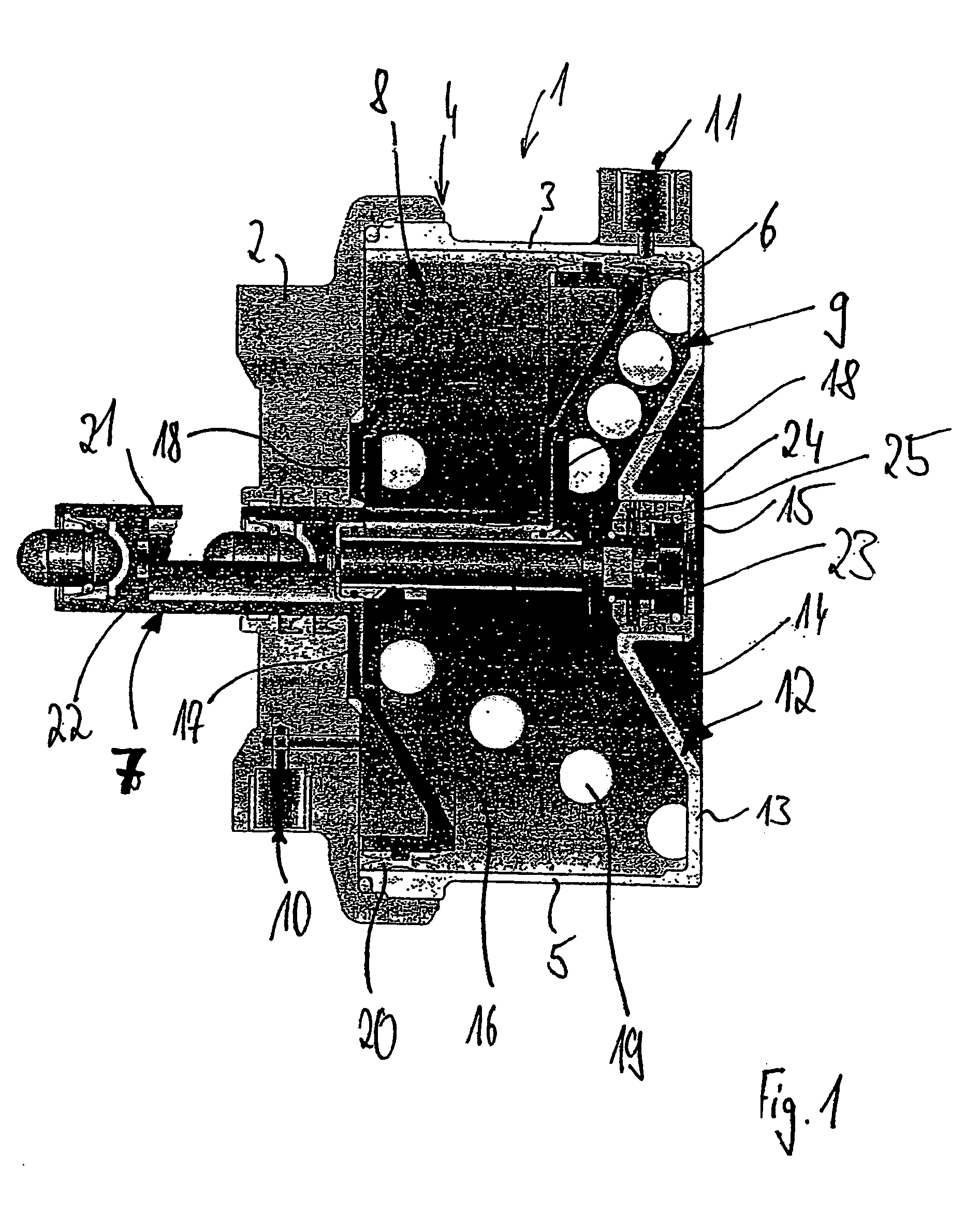
[0023]FIG. 1 shows a combined pneumatic cylinder 1, with which the service, auxiliary and parking brake function of a brake of the vehicle can be realized.

[0024] Here, the combined pneumatic cylinder 1 has a (screwed) brake cylinder housing 4, which is composed of a cover part 2 and a cup-shaped part 3 and in which a piston 6 is guided displaceably, which piston 6 is arranged on a piston rod 7 which penetrates the cover part 2 of the brake cylinder housing 4 and is designed for the purpose of actuating the associated brake, preferably a disc brake.

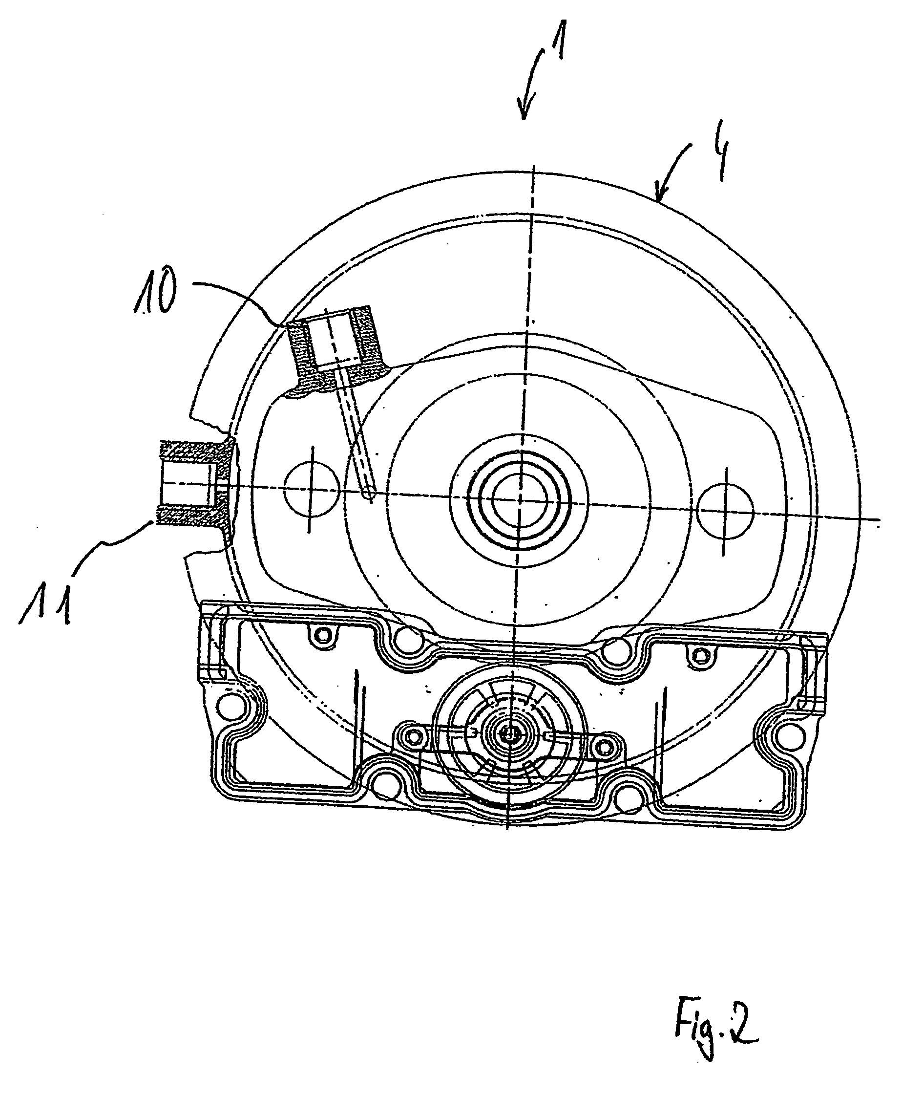
[0025] The piston 6 divides the interior of the brake cylinder housing 4 into a first pressure space 8 (here, shown on the left) and a second pressure space 9 (here, shown on the right), into which in each case a compressed air connection 10, 11 which penetrates the outer wall of the brake cylinder housing 4 opens.

[0026] The first cup-shaped part 3 has a cylindrical cover 5 and a basic section 12.

[0...


PUM


Abstract

A combined pneumatic cylinder and a corresponding control method are characterized in that a spring for realizing the parking brake function is directly placed inside one of two pressure chambers and, to be precise, inside the pressure chamber that is designed for effecting service brakings by increasing pressure. The service brake function as well as the parking brake function can be realized by means of only two pressure chambers and the spring.

Description

CROSS REFERENCE TO RELATED APPLICATIONS [0001] This application is a continuation of PCT International Application No. PCT / EP2004 / 014476, filed on Dec. 20, 2004, which claims priority under 35 U.S.C. § 119 to German Patent Application No. 103 60 879.6, filed Dec. 23, 2003, the entire disclosures of which are herein expressly incorporated by reference.BACKGROUND AND SUMMARY OF THE INVENTION [0002] The invention relates to a combined pneumatic cylinder for a vehicle brake and to a method for controlling a combined pneumatic cylinder of this type. [0003] Different designs of combined pneumatic cylinders are known. They generate the braking forces for the service brake, the parking brake and, in general, also for the auxiliary brake function of the vehicle. Combined pneumatic cylinders for pneumatically actuated disc brakes often have a service brake cylinder section (for example, a diaphragm cylinder) which is attached to the parking brake cylinder section, in which the helical spring ...

Claims


Application Information

Patent Timeline
IPC IPC(8): F16F9/12F16D65/28B60T13/38F16D65/14
CPCB60T13/38F16D2121/14F16D2121/02F16D65/28
Inventor BAUMGARTNER, JOHANNSIEBKE, ALF
Owner KNORR-BREMSE SYST FUER NUTZFAHRZEUGE GMBH
Why Eureka
Try Eureka