Motor vehicle clutch linkage lubrication

Inactive Publication Date: 2007-02-01
ZF FRIEDRICHSHAFEN AG
View PDF16 Cites 4 Cited by
  • Summary
  • Abstract
  • Description
  • Claims
  • Application Information

AI Technical Summary

Benefits of technology

[0006] Thus it is an object of the present invention to provide various means for ensuring the consistent presence of lubrication on motor vehicle clutch components.

Problems solved by technology

Both the location and operation of a manual motor vehicle clutch suggests the difficulty of its existence.
Due to the expense of replacing the clutch, which includes not only replacement components and labor but also the down time of the vehicle, it is not surprising that significant effort has been undertaken to improve and extend the service life of the clutch.

Method used


Image

  • Motor vehicle clutch linkage lubrication
  • Motor vehicle clutch linkage lubrication
  • Motor vehicle clutch linkage lubrication

Examples


first embodiment

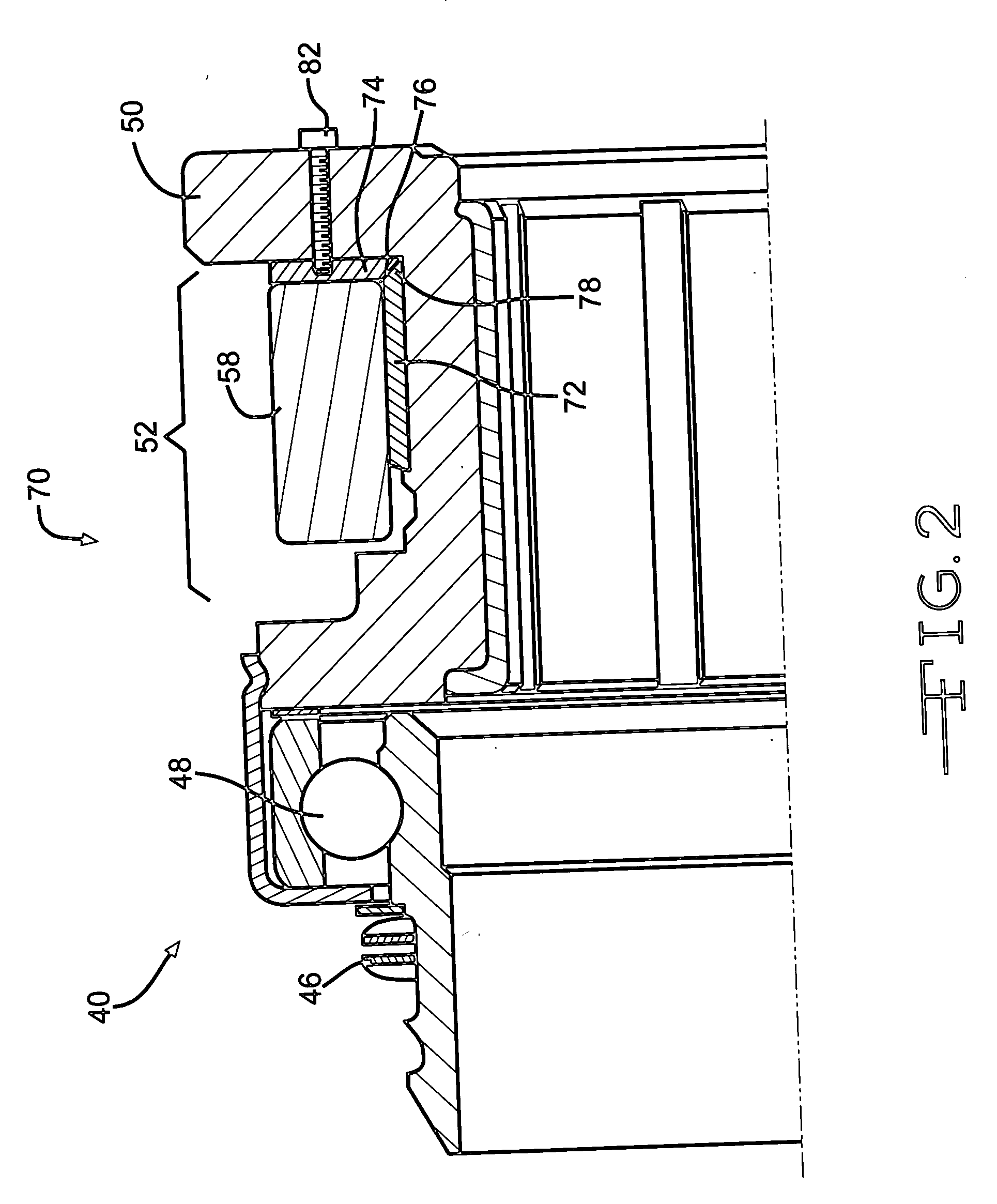
[0022] Referring now to FIG. 2, a first embodiment lubrication arrangement for the manual clutch release bearing 50 is illustrated. As noted, the release bearing 50 includes a circumferential groove or channel 52 which receives a pair of spaced apart shift arms 58 of the release fork 60, one of which is illustrated in FIG. 2. Disposed within the circumferential channel 52 of the release bearing 50 is a first cylindrical oil or grease impregnated bronze insert 72 and a second annular oil impregnated bronze insert 74 disposed at a right angle to the first oil or grease impregnated insert 72. Together, the oil or grease impregnated bronze inserts 72 and 74 fully cover the surfaces of the release hub or bearing 50 against which the release arms 58 engage. Hence, friction is reduced relative to non-oil impregnated components and the service life of both the release arms 58 and the release hub or bearing 50 are improved. The oil or grease impregnated bronze inserts 72 and 74 may be of any...

fourth embodiment

[0025] Referring now to FIG. 5, a manual clutch release bearing lubrication arrangement is illustrated and designated by the reference number 110. Here, a pair of zirc fittings 112 each disposed proximate the end of the release fork 58, one of which is illustrated in FIG. 5, communicate with a passageway 114 which receives, stores and distributes grease 116 to the contacting and frictional features of the arms 58 of the release fork 60 and the release bearing 50. Similarly, a grease or zirc fitting 118 disposed in a central portion of the release fork 60 communicates through a passageway 122 with the release fork pivot pin 62 and provides a lubricant such as grease 124 into this region to reduce friction and improve the service life of these components.

fifth embodiment

[0026] Referring now to FIG. 6, a fifth embodiment manual clutch release bearing lubrication arrangement is illustrated and designated by the reference number 130. Here, a single grease or zirc fitting 132 communicates with a plurality of passageways, a first passageway 134 communicating and providing a lubricant such as grease to the pivot pin 62 and a second pair of diverging passageways 136A and 136B which carry the lubricant to each terminal portion of the release forks 58 and provides such lubricant to the points of contact to reduce sliding friction and improve the service life of the components.


PUM


Abstract

Several distinct motor vehicle clutch fork and release bearing lubrication arrangements which may be utilized singly or in various combinations include: oil impregnated inserts, self-lubricating pockets, single or multiple central grease fittings in communication with passageways that provide grease to contact and bearing surfaces and sealed boots filled with lubricant which cover a portion of ends of the release fork.

Description

BACKGROUND OF THE INVENTION [0001] The invention relates generally to motor vehicle clutches of the manual type and more specifically to manual motor vehicle clutches having various arrangements for providing and improving lubrication of certain components. [0002] Both the location and operation of a manual motor vehicle clutch suggests the difficulty of its existence. A typical manual motor vehicle clutch is disposed behind the prime mover which is typically an internal combustion gas or Diesel engine and a head of the transmission. In service, it is called upon to repeatedly connect and disconnect the driving force of the engine to the transmission. Hundreds of horsepower, hundreds of foot pounds of torque, thousands of revolutions per minute and thousands of operating cycles characterize its operating environment. [0003] Sandwiched between the prime mover and transmission of a vehicle, replacing or even servicing a manual clutch is a project to reckon with. Due to the expense of ...

Claims


Application Information

Patent Timeline
IPC IPC(8): F16D19/00F16D13/00
CPCF16D23/14F16D2300/06F16D2023/141F16D23/148F16D13/50
Inventor SAMRA, MUNEER ABU
Owner ZF FRIEDRICHSHAFEN AG
Why Eureka
Try Eureka