Mounting assembly for a vibration damper

a technology of vibration damper and mounting assembly, which is applied in the direction of shock absorbers, mechanical equipment, transportation and packaging, etc., can solve the problems of difficult design of efficient assembly lines, lack of assembly robots, and inability to introduce vibration dampers, so as to achieve the effect of reducing the usable space inside the mounting cap and significantly increasing the thickness of the wall

Inactive Publication Date: 2007-02-01
ZF FRIEDRICHSHAFEN AG
View PDF6 Cites 4 Cited by
  • Summary
  • Abstract
  • Description
  • Claims
  • Application Information

AI Technical Summary

Benefits of technology

[0009] The advantage of the invention consists in that the mounting cap fulfills two support functions; that is, it supports the vibration damper on the carrier and supports the carrier on the vehicle body. For the course of the installation process, what results is the decisive advantage that, after the installer has introduced the complete module consisting of the mounting assembly and the vibration damper through the wheelhouse and into the body and the mounting assembly has aligned itself automatically in the circumferential direction so that the fastening means between the mounting assembly and the body are aligned, the mounting cap then holds the entire assembly in the installation position. After that, the same installer can secure the fastening means by reaching through the open hood or trunk lid.
[0010] It is also advantageous for the at least one tongue to be present in the space defined by the mounting cap. Use is thus made of the space which is available in any case as a result of the conical shape of the mounting cap. There is no need to provide any axial space.
[0011] The mounting cap should be kept as light in weight and therefore as thin-walled as possible. For this reason, the at least one opening is designed independently of the torque-transmitting connection between the mounting cap and the carrier. If the opening, together with the tongue, is designed to absorb torsional forces, then the wall thickness would have to be significantly increased, and in turn the usable space inside the mounting cap would decrease to the same extent.
[0012] The mounting cap has at least one inside wall, in which the opening for the tongue is provided. The inside wall is subjected only to tensile force by the tongue.
[0013] The tongue is designed as an L-shaped web of the carrier. This shape easily creates an axial offset between the top of the carrier and the free end of the tongue. The size of the axial offset determines the axial depth to which the tongue penetrates into the space defined by the mounting cap.
[0014] The inside wall is provided with a certain radial elasticity, so that the tongue of the carrier does not have to execute any radial movement during installation. To promote easy installation, the bottom end of the at least one inside wall has a feed bevel facing the tongue. On contact with the tongue, this bevel causes the inside wall to deflect in the radial direction, which allows the tongue to slide more easily into the opening.

Problems solved by technology

No assembly robot is available in that situation for precisely installing the vibration damper.
During installation in a new vehicle, the problem occurs that the vibration damper must be introduced from the underside of the vehicle, whereas an installer must install the fastening means, usually threaded nuts, from above.
These installation sequences make it difficult to design an efficient assembly line.

Method used


Image

  • Mounting assembly for a vibration damper
  • Mounting assembly for a vibration damper
  • Mounting assembly for a vibration damper

Examples


Embodiment Construction

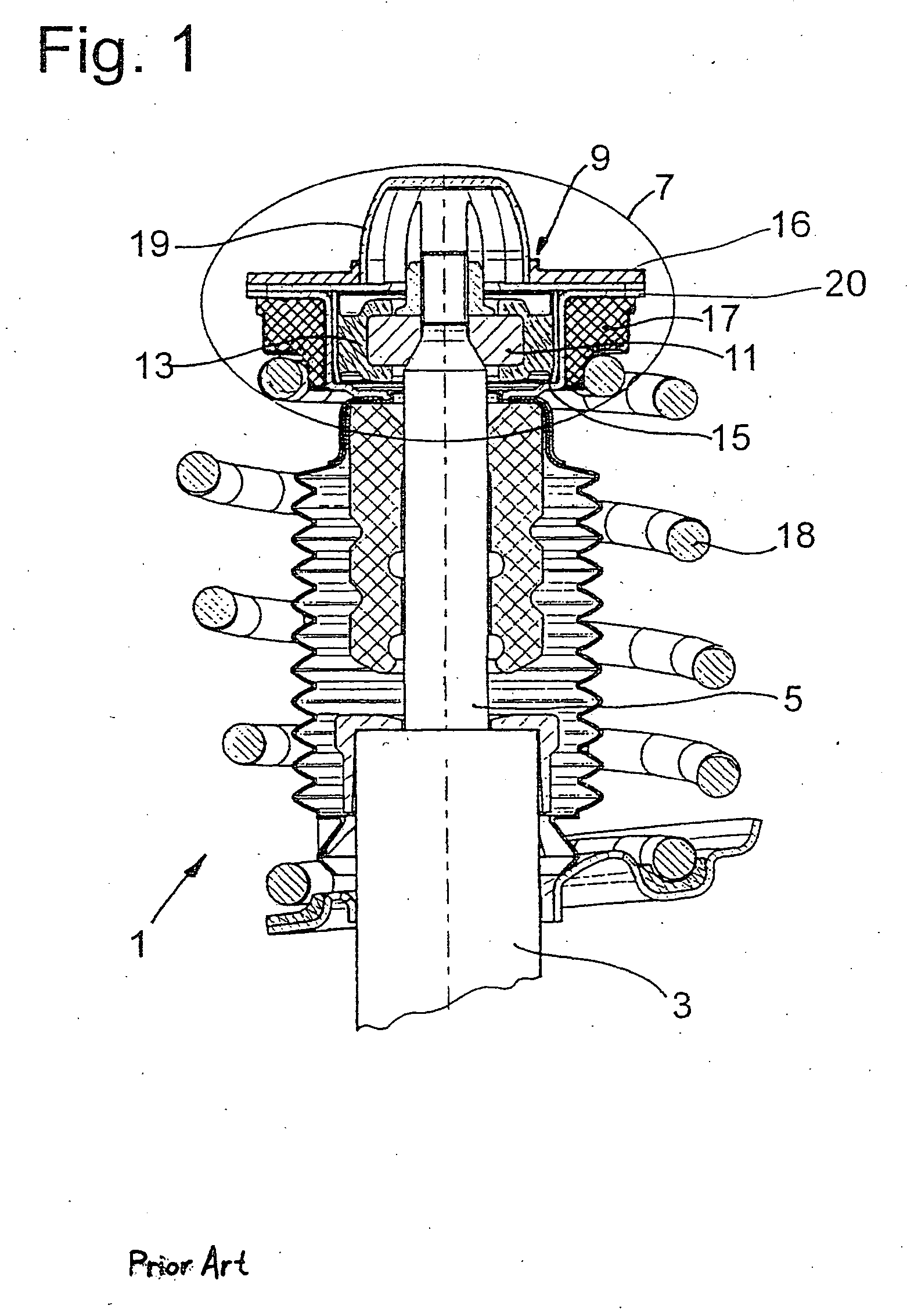
[0028]FIG. 1 shows the installation situation at the upper end of a vibration damper 1, which comprises a cylinder 3, in which a piston rod 5 is supported with freedom of axial movement. At its outer end, the piston rod has a mounting assembly 7 for attachment to a vehicle, of which only a receiving opening 9 in a carrier is shown. A receiving opening of this type can be, for example, provided in an inside fender of the vehicle.

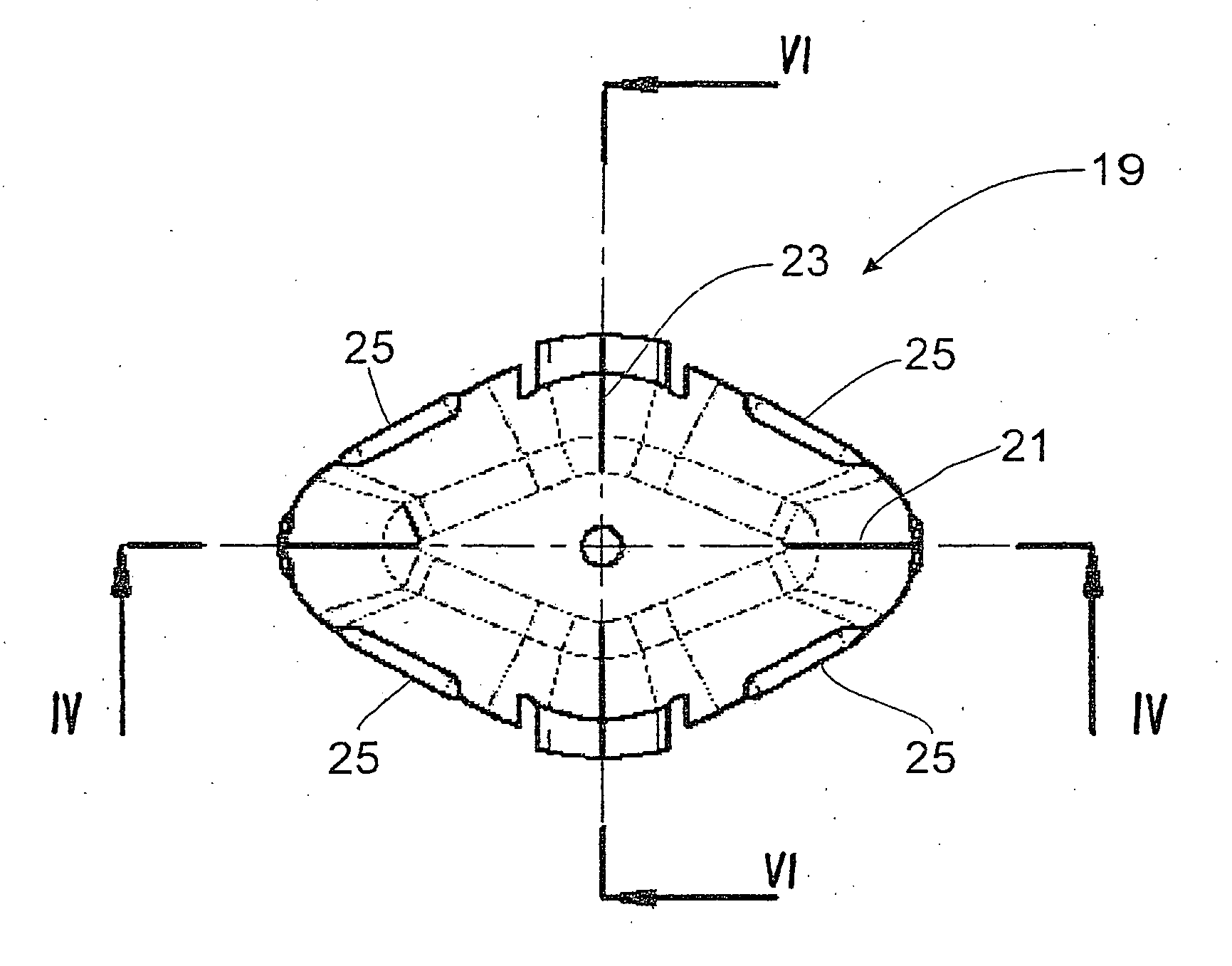
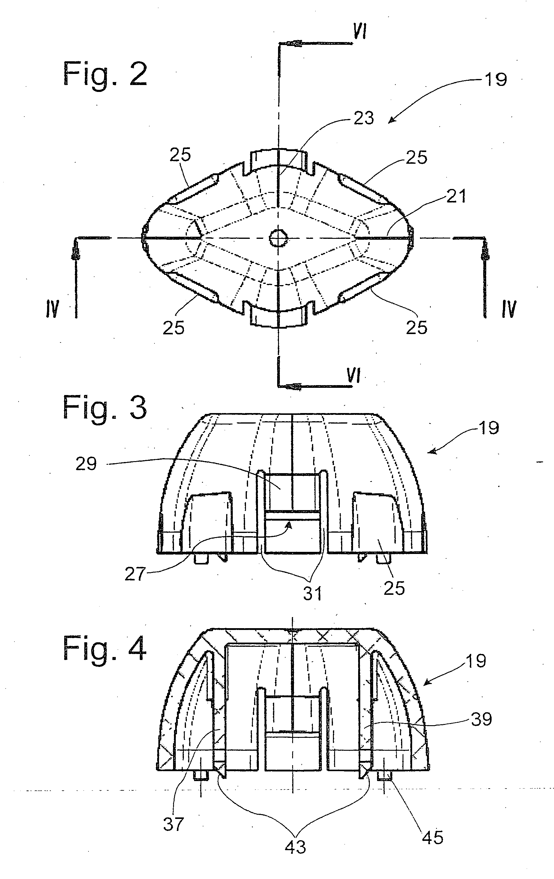
[0029] The mounting assembly 7 comprises a support body 11, which is at least partially enclosed by a spring element 13. The spring element in turn is enclosed by a two-part mounting housing 15 consisting of a carrier 16 and a mounting cup20, on the outside surface of which a spring base 17 for a vehicle suspension spring 18 is supported. The entire mounting assembly is covered by a mounting cap 19.

[0030]FIGS. 2-7 show the mounting cap according to FIG. 1 as an isolated part. In the top view of FIG. 2, it can be seen that the mounting cap 19 has an elliptic...


PUM


Abstract

Mounting assembly for a vibration damper, comprising at least one aligning surface on the vibration damper side, which is in working connection with an opposing surface on the vehicle side at least during the installation of the vibration damper in a receiving opening in the vehicle. The at least one aligning surface and the opposing surface rotationally align the mounting side with the vehicle side. The aligning surface is arranged on a mounting cap with torque-transmitting element, and with at least one axial support surface for cooperation with the opposing surface on the vehicle side. The mounting cap prevents the vibration damper from falling out of the mounting assembly through the use of a carrier on the mounting side, to which the vibration damper is attached, this carrier having a retaining element in the form of a tongue which engages an opening in the mounting cap.

Description

BACKGROUND OF THE INVENTION [0001] The invention relates to a mounting assembly for a vibration damper. [0002] U.S. Pat. No. 6,572,089, which represents the state of the art, describes a mounting assembly for a vibration damper, comprising at least one surface, which is in working connection with an opposing surface on the vehicle side at least during the installation of the vibration damper in a receiving opening in the vehicle, where the at least one surface and the opposing surface rotationally align connecting means on the mounting side with connecting means on the vehicle side. The at least one surface of the mounting assembly is arranged on a mounting cap, which is in working, torque-transmitting connection with the overall mounting assembly. [0003] The great advantage of a mounting cap of this type is that, during the assembly process, the vibration damper can be introduced into the installation location more-or-less imprecisely with respect to its alignment in the circumfere...

Claims


Application Information

Patent Timeline
Patent Type & Authority Applications(United States)
IPC IPC(8): B60G13/00B60G15/00
CPCB60G15/068B60G2202/312B60G2206/931B60G2204/45021B60G2206/91B60G2204/4404
Inventor PFLAUM, THOMASFREISINGER, CLAUDIUS
Owner ZF FRIEDRICHSHAFEN AG
Why Eureka
Try Eureka