

Air bag device
a technology of airbags and bags, which is applied in the direction of vehicular safety arrangements, pedestrian/occupant safety arrangements, vehicle components, etc., can solve the problems of difficult to properly control the pressure within the bag member, passenger strikes and rebounds, etc., to achieve effective restraint of passengers, quick inflation and expansion, and effectively relieve impact energy acting on passengers
- Summary
- Abstract
- Description
- Claims
- Application Information
AI Technical Summary
Benefits of technology
Problems solved by technology
Method used
Image

Examples
first embodiment
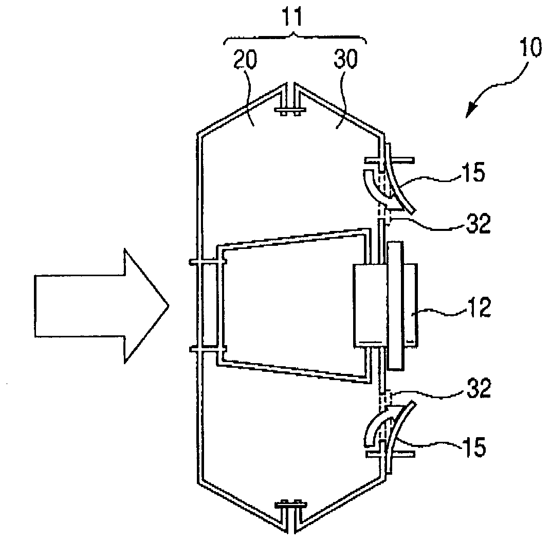
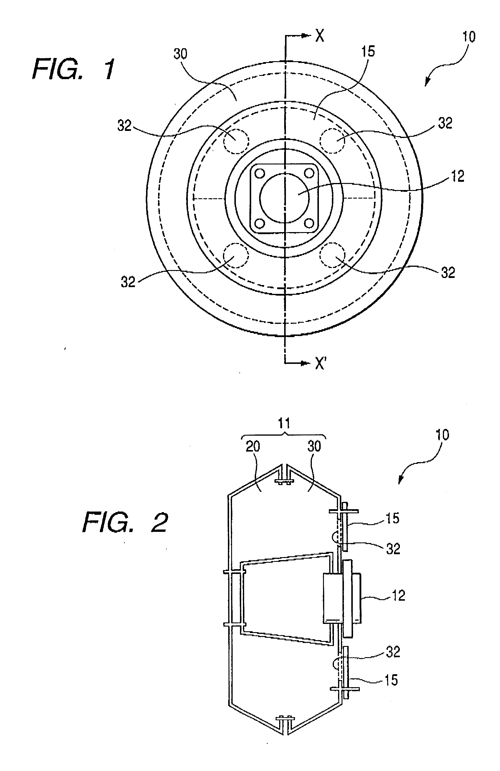
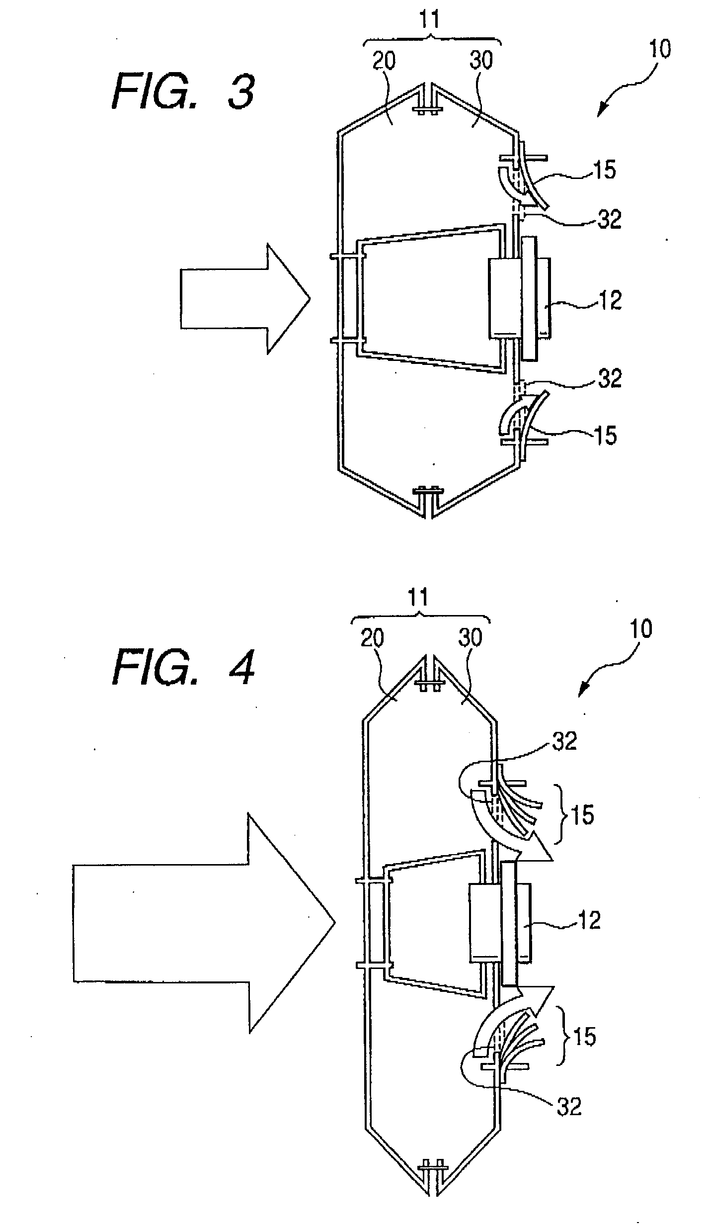
[0032]FIG. 1 is a rear view of an air bag device 10 of this embodiment. FIG. 2 is a schematic cross-sectional view of the air bag device 10 taken along the line X-X′ of FIG. 1. The air bag device 10 is mounted on a steering wheel body (not shown) mounted on a distal end of a steering shaft (not shown) suitably adjustably tilted. The air bag device 10 is supported by a base plate (not shown) made of metal or other material, and a cover member (not shown) made of a synthetic resin is attached to this base plate. In this air bag device 10, an bag member 11 is inflated by gas generated by an inflator 12 at the time of a frontal collision of a vehicle to break the cover member, and is expanded from a central portion of the steering wheel body toward a passenger compartment, thereby restraining the passenger so as to protect the passenger from an impact of a secondary collision.
[0033] The air bag device 10 mainly comprises the bag member 11 and the inflator 12 for generating gas at the t...
second embodiment
[0037] An air bag device of the second embodiment is similar in construction to the air bag device of the first embodiment except that a lid member has a different shape and different sewn portions. FIGS. 5 and 6 are plan views respectively showing the lid member 15 of the air bag device of the first embodiment and the lid member 16 of the air bag device of the second embodiment. As shown in these figures, the lid member 15 has the circular annular shape, while the lid member 16 has a substantially square annular shape, and is sewn to a reverse-side cloth at its outer peripheral edge portion except apex portions (that is, four corner portions) thereof.
[0038] The operation of the air bag device of the second embodiment is basically similar to the operation of the air bag device 10 of the first embodiment. The only difference is that gas is discharged not only through an inner peripheral edge portion of the lid member 16 but also through the apex portions thereof at the time of infla...
third embodiment
[0039] An air bag device of the third embodiment is similar in construction to the air bag device of the second embodiment except that four sides of a lid member of a substantially square annular shape are curved inwardly or concavely. FIG. 7 is a plan view showing the lid member 17 of the air bag device of the third embodiment. As shown in FIG. 7, the lid member 17 is sewn to a reverse-side cloth at its outer peripheral edge portion except apex portions (that is, four corner portions) thereof.
[0040] The operation of the air bag device of the third embodiment is similar to the operation of the air bag device of the second embodiment. Namely, the third embodiment is similar to the second embodiment in that gas is discharged not only through an inner peripheral edge portion of the lid member 17 but also through the apex portions thereof at the time of inflation and expansion of the air bag member, since the apex portions of the lid member 17 are not sewn to the reverse-side cloth. Th...
PUM
 Abstract
Description
Claims
Application Information