
Lens barrel

Inactive Publication Date: 2007-02-01
FUJIFILM CORP
View PDF15 Cites 4 Cited by
  • Summary
  • Abstract
  • Description
  • Claims
  • Application Information

AI Technical Summary

Benefits of technology

[0008] According to the present invention, since the device which varies the open F value is provided separately from a usual diaphragm device for exposure control, individual construction and control are made possible, and construction in structure or control is simplified compared with a case where the open F value is limited by the usual diaphragm device.
[0010] According to the present invention, when the focal length is changed, the open F value varying device varies the open F value to an appropriate value according to the focal length in mechanical conjunction with that. Thus, special control of the open F value varying device is not required and the open F value can be varied with a high accuracy.
[0014] According to the present invention, since the open F value varying device is provided separately from the diaphragm device, the diaphragm device can be a manually operated diaphragm as in the present invention, and an F value can be set with a higher accuracy as compared with an electrically operated one. Also, since there is no need to provide a mechanism for limiting the open F value at the diaphragm device by providing the open F value varying device separately from the diaphragm device as in the present invention, there is no such a problem that the structure is complicated, but an appropriate open F value can be set without considering limitation of the opening amount at diaphragm control so that the optical performance is not deteriorated.
[0015] According to the lens barrel of the present invention, change of the open F value according to the focal length can be carried out with a simple mechanism and with a high accuracy so that the optical performance is not deteriorated.

Problems solved by technology

However, according to Japanese Patent No. 3610113, since the open F value is limited by limiting on control a maximum opening amount of a diaphragm for exposure control to be controlled by a motor such as an IG meter, there is a problem that diaphragm control gets complicated and delayed.
There is also another problem that the diaphragm for exposure control can not be manually operated.

Method used


Image

  • Lens barrel
  • Lens barrel
  • Lens barrel

Examples


Embodiment Construction

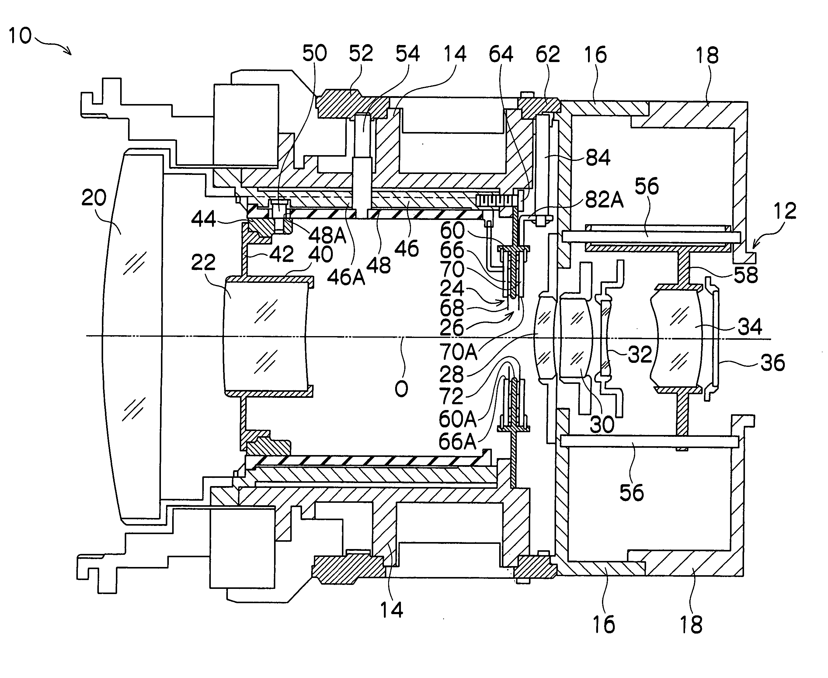
[0022] A preferred embodiment of the lens barrel according to the present invention will be described below referring to the attached drawings.

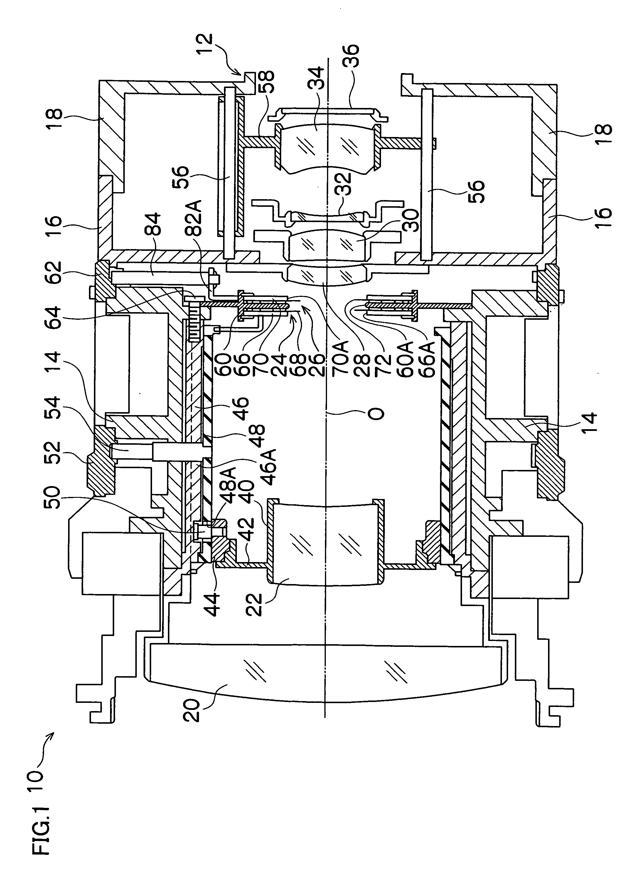
[0023]FIG. 1 is a side sectional view showing a lens barrel of a zoom lens used in an ENG camera, a video camera, a monitor camera or the like, for example, to which the present invention is applied.

[0024] A lens barrel 10 in this figure is provided with a lens mount 12, whose detail is omitted, formed at its rear end and is detachably attached to a camera head, not shown, by this lens mount 12.

[0025] A fixed cylinder of the lens barrel 10 comprises a front fixed cylinder 14, a middle fixed cylinder 16 and a rear fixed cylinder 18 connected in series, and each of members constituting the lens barrel 10 is supported by these fixed cylinders 14, 16, 18.

[0026] On an optical axis 0 of the lens barrel 10, there are arranged as an optical system for forming an image of a subject in order from the object side, a fixed lens (group) 20, a zoom len...


PUM


Abstract

The present invention provides a lens barrel having an optical system capable of change of a focal length, comprising: a diaphragm device which controls a light amount of light incident to the optical system and passing to an image forming surface; and an open F value varying device which is provided separately from the diaphragm device, controls a light amount of the light incident to the optical system and passing to the image forming surface and varies an open F value by limiting the light amount so that the open F value becomes a value according to a focal length of the optical system when the light amount which is controllable by the diaphragm device is at the maximum.

Description

BACKGROUND OF THE INVENTION [0001] 1. Field of the Invention [0002] The present invention relates to a lens barrel and particularly to a lens barrel having a diaphragm mechanism for changing an open F value according to a focal length in a zoom lens (image pickup lens with variable focal length). [0003] 2. Description of the Related Art [0004] A zoom lens with a variable focal length in which an open F value is adjusted according to a focal length by limiting a maximum opening amount of a diaphragm is proposed in Japanese Patent No. 3610113. According to this, with a trend of size reduction and higher magnification of a zoom lens, a defocus amount (spherical aberration) tends to get bigger when the diaphragm is opened, and thus, it is proposed that the maximum opening amount of the diaphragm is limited to the extent that the defocus amount does not become poor. That is, an F value when the diaphragm is not opened to the maximum is set as an open F value, and it is so constituted tha...

Claims


Application Information

Patent Timeline
IPC IPC(8): G02B9/08G02B7/02G02B7/10G03B9/02G03B9/06
CPCG03B9/06G02B7/10
Inventor TAKEDA, TOSHIAKIMORI, YOSHITAKA
Owner FUJIFILM CORP
Learn More