
Method for programming non-volatile memory with self-adjusting maximum program loop

a non-volatile memory and maximum program loop technology, applied in static storage, digital storage, instruments, etc., can solve the problems of inability to adjust the maximum program loop, and inability to accurately detect errors, etc., to achieve the effect of not increasing the incidence of errors

Active Publication Date: 2007-02-01
SAMSUNG ELECTRONICS CO LTD +1
View PDF24 Cites 133 Cited by
  • Summary
  • Abstract
  • Description
  • Claims
  • Application Information

AI Technical Summary

Benefits of technology

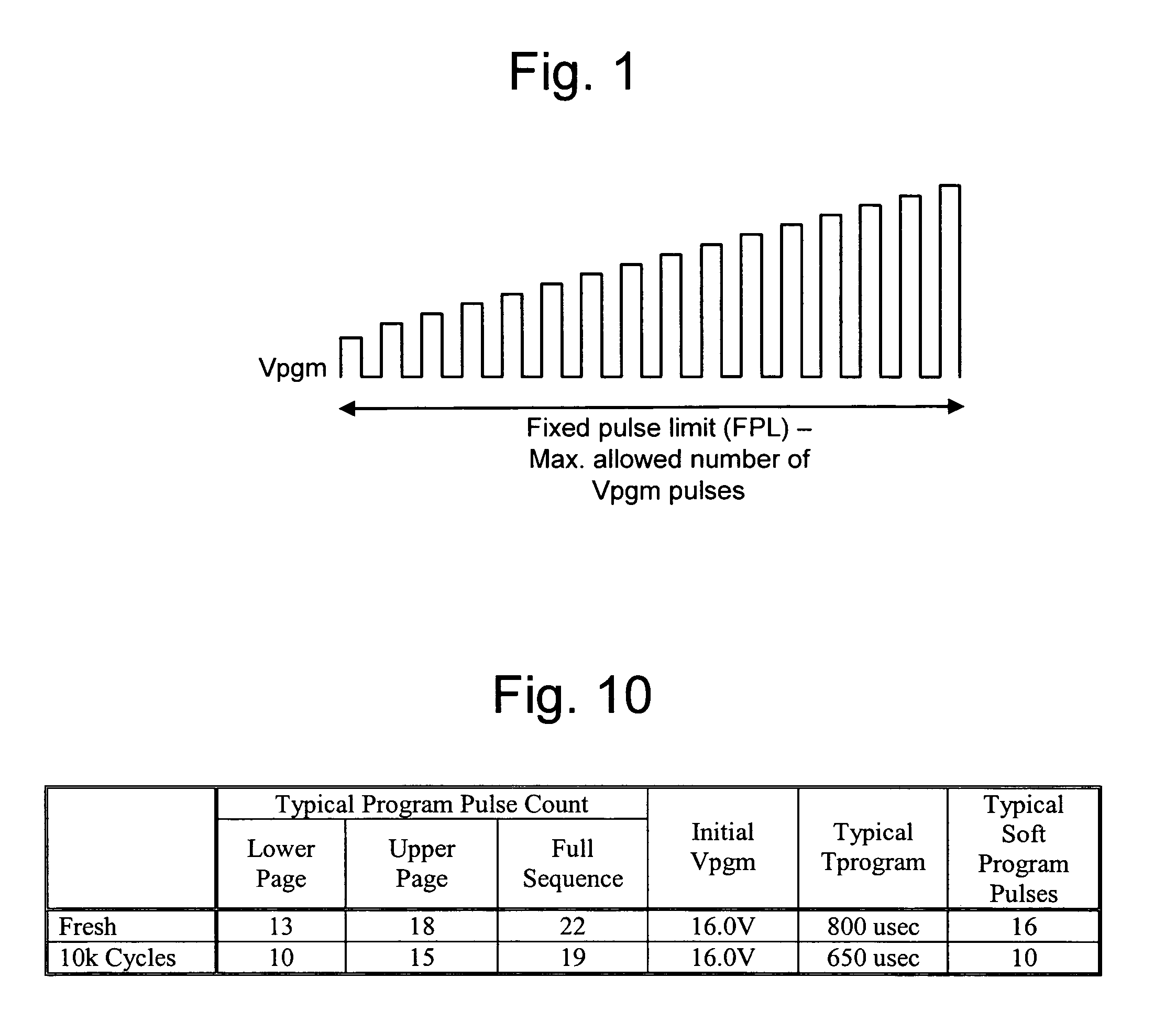
The present invention provides a method for programming non-volatile memory without increasing the incidence of errored elements. This is achieved by adjusting the number of program voltage pulses that are applied to the elements in a non-volatile memory based on the freshness of the memory devices. The method includes programming at least one non-volatile storage element to reach a verify level using a series of voltage pulses, and detecting when the non-volatile storage element has reached the verify level. The method further includes enforcing a maximum allowable number of additional voltage pulses to be used in programming at least one other non-volatile storage element to reach a second verify level. This method improves the programming accuracy and reliability of non-volatile memory devices.

Problems solved by technology

In particular, if the initial value or the step size is too large, some memory elements may be over-programmed, resulting in an inaccurate threshold voltage, while longer programming times will result if the initial value or the step size is too small.
However, if one normal page of memory elements has several slow elements or has one bad column, the entire page will keep programming until the maximum number of pulses has occurred.
As a result, some elements along the same word line as the slow element or the bad column could be disturbed.
Moreover, this scenario is more severe for cycled devices, which have undergone many programming cycles, than for fresh devices, which have not been significantly used, because the cycled devices are faster than fresh devices due to charge trapping.
In particular, as a non-volatile memory device undergoes many programming cycles, charge becomes trapped in the insulator or dielectric between the floating gate and the channel region.
This trapping of charge shifts the threshold voltage to a higher level, which allows the memory element to program quicker while also making it harder to erase the charge in the element.
If the magnitude of the program signal is set too high, even though it does not result in over programming of a fresh device, as that device becomes more heavily used, that device may experience over programming.
Consequently, an excessive number of program pulses may be applied to the normal elements in the cycled device.
The problem is exacerbated by the fact that cycled devices have more bad columns than fresh devices.
While it is possible to lower the number of Vpgm pulses used before declaring an error condition, as mentioned, this reduces yield.
For example, if the maximum number of program pulses is reduced from twenty-four to twenty-two, the die-sort yield is reduced by about 5%, which is generally considered to be unacceptable.

Method used


Image

  • Method for programming non-volatile memory with self-adjusting maximum program loop
  • Method for programming non-volatile memory with self-adjusting maximum program loop
  • Method for programming non-volatile memory with self-adjusting maximum program loop

Examples


Embodiment Construction

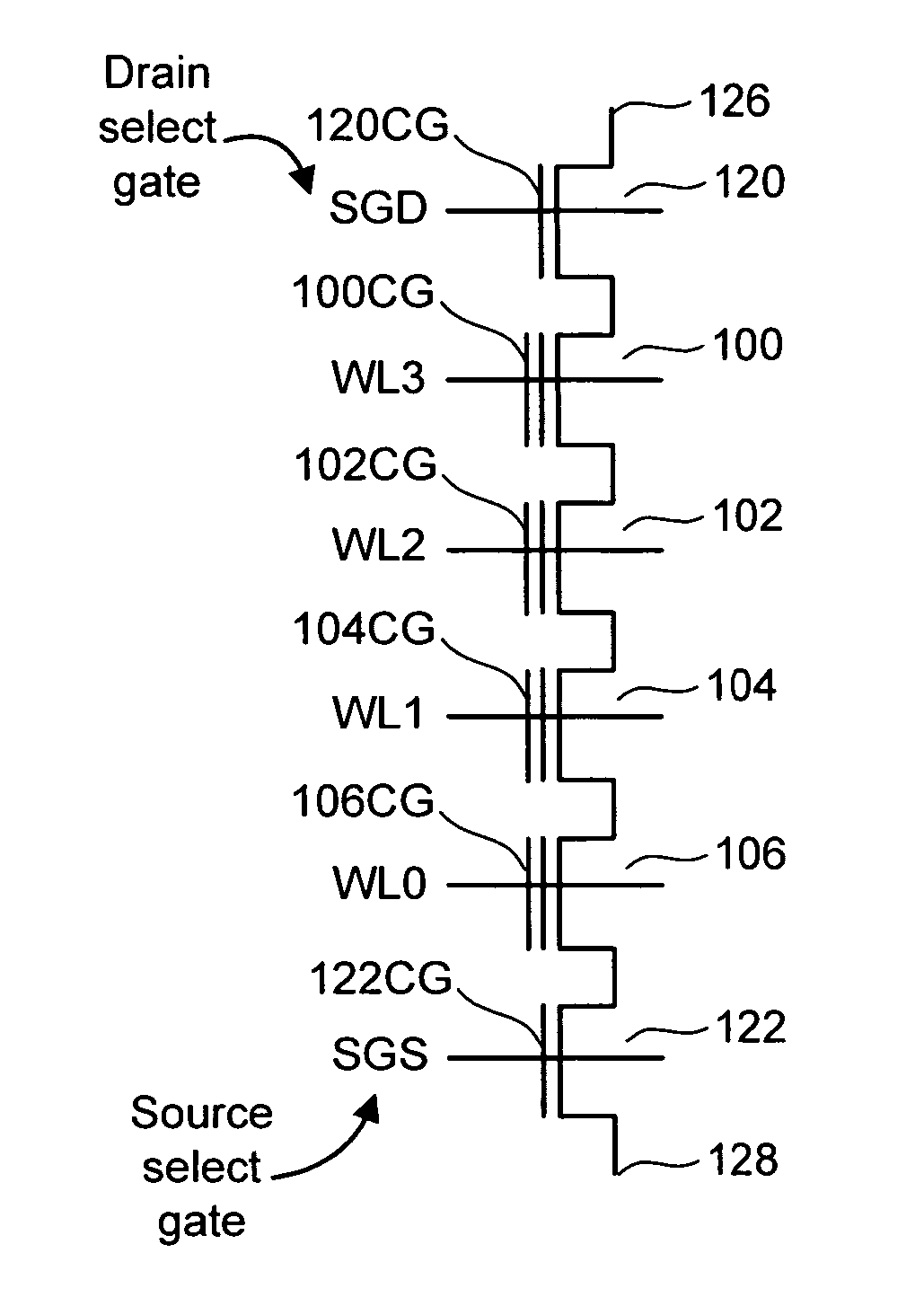
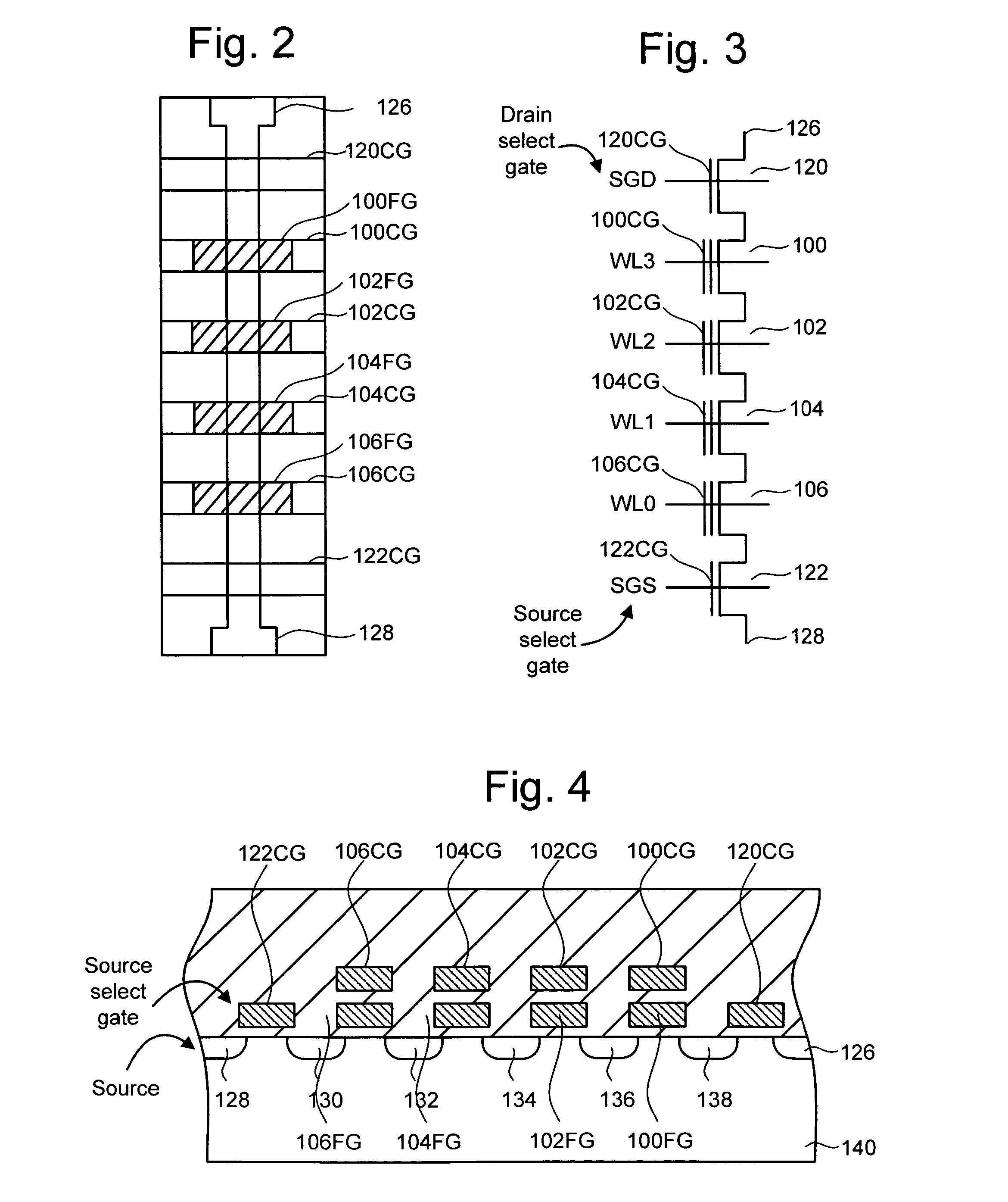
[0032] One example of a non-volatile memory system suitable for implementing the present invention uses the NAND flash memory structure, which includes arranging multiple transistors in series between two select gates. The transistors in series and the select gates are referred to as a NAND string. FIG. 2 is a top view showing one NAND string. FIG. 3 is an equivalent circuit thereof. The NAND string depicted in FIGS. 2 and 3 includes four transistors, 100, 102, 104 and 106, in series and sandwiched between a first select gate 120 and a second select gate 122. Select gate 120 connects the NAND string to bit line contact 126. Select gate 122 connects the NAND string to source line contact 128. Select gate 120 is controlled by applying the appropriate voltages to control gate 120CG. Select gate 122 is controlled by applying the appropriate voltages to control gate 122CG. Each of the transistors 100, 102, 104 and 106 has a control gate and a floating gate. Transistor 100 has control gat...


PUM


Abstract

The maximum allowable number of voltage programming pulses to program memory elements of a non-volatile memory device is adjusted to account for changes in the memory elements which occur over time. Programming pulses are applied until the threshold voltage of one or more memory elements reaches a certain verify level, after which a defined maximum number of additional pulses may be applied to other memory elements to allow them to also reach associated target threshold voltage levels. The technique enforces a maximum allowable number of programming pulses that can change over time as the memory is cycled.

Description

CROSS-REFERENCE TO RELATED APPLICATIONS [0001] This application is related to co-pending, commonly assigned U.S. patent application Ser. No. ______, titled “System For Programming Non-Volatile Memory With Self-Adjusting Maximum Program Loop”, by Jun Wan and Jeffrey W. Lutze, filed on the same date herewith, (attorney docket no. SAND-1050US1), incorporated herein by reference in its entirety.BACKGROUND OF THE INVENTION [0002] 1. Field of the Invention [0003] The present invention relates to programming non-volatile memory. [0004] 2. Description of the Related Art [0005] Semiconductor memory has become increasingly popular for use in various electronic devices. For example, non-volatile semiconductor memory is used in cellular telephones, digital cameras, personal digital assistants, mobile computing devices, non-mobile computing devices and other devices. Electrically Erasable Programmable Read Only Memory (EEPROM) and flash memory are among the most popular non-volatile semiconducto...

Claims


Application Information

Patent Timeline
Patent Type & Authority Applications(United States)
IPC IPC(8): G11C11/34G11C16/06G11C16/04
CPCG11C11/5628G11C16/0483G11C2211/5621G11C16/3454G11C16/3459G11C16/10
Inventor WAN, JUNLUTZE, JEFFREY W.
Owner SAMSUNG ELECTRONICS CO LTD
Learn More