Unlock instant, AI-driven research and patent intelligence for your innovation.

Information recording method and information recording device

a recording method and information technology, applied in the direction of recording signal processing, television systems, instruments, etc., can solve the problems of insufficient release of heat in the direction of disc film thickness, edge shift, and track direction producing problems, so as to reduce the leading edge shift of succeeding marks

Inactive Publication Date: 2007-02-01
HITACHI CONSUMER ELECTRONICS CORP
View PDF7 Cites 5 Cited by
  • Summary
  • Abstract
  • Description
  • Claims
  • Application Information

AI Technical Summary

Benefits of technology

[0009] (1) When a space is formed after the monopulse that forms a recording mark, a downward pulse is applied on the backside of the midpoint of the space. In the case of an optical disc, in many cases, laser light is used as an energy beam, a multipulse or monopulse waveform is used at a mark portion, and a non-pulse waveform, namely uniform power, is used for irradiation at a space. In the case of a medium wherein heat transfer in the film plane direction is violent, heat generated by the energy irradiation to the space propagates to the trailing edge of the mark recorded immediately before the space and / or the leading edge of the mark recorded immediately after the space. Therefore, in the present invention, in the case of a medium wherein the edge shift of the leading edge of a mark recorded in the next place is conspicuous for example, the effect of heat insulation is secured by: inserting a downward pulse in the back portion of a space near the position of the leading edge; and thereby lowering the average irradiation power of the space below that of the front portion thereof. Thereby, it is possible to reduce the leading edge shift of the succeeding mark.
[0021] As stated above, it is possible to reduce the leading edge shift of a succeeding mark by lowering the average irradiation power of a space below that of the front portion thereof and producing the effect of heat shield.

Problems solved by technology

However, in the case of recording information on a multi-layered disc having information faces in plural layers, the edge shift caused by the thermal interference in the track direction produces a problem.
However, since an information layer on the side of the incidence of light is required to have a high permeability, an alloyed reflective film having a film thickness enough to allow a sufficient thermal diffusion effect cannot be formed and as a result the release of the heat in the disc film thickness direction is insufficient.
As a consequence, the arising problem here has been that, in the recording on a semitransparent layer, the heat propagates in the recording film plane direction, the temperature rises at the edge of an adjacent mark, and edge shift is caused.
The problem has been conspicuous in the case of high-speed recording that uses a monopulse waveform.
However, in comparison with an N−1 system strategy and a 2T system strategy, in the case of the monopulse waveform, a larger amount of energy is applied in a short period of time and hence a bias power cooling effect during the forming of a recording mark, which is seen in the case of a multipulse waveform, cannot be obtained.
As a consequence, the arising problem here has been that the thermal interference between the preceding and succeeding marks becomes more conspicuous and edge shift tends to appear.
In particular, in the case of high-speed monopulse recording on an information layer having a semitransparent recording layer, the edge shift has been violent.

Method used


Image

  • Information recording method and information recording device
  • Information recording method and information recording device
  • Information recording method and information recording device

Examples


first embodiment

[0038] An embodiment according to the present invention is hereunder explained in reference to the drawings.

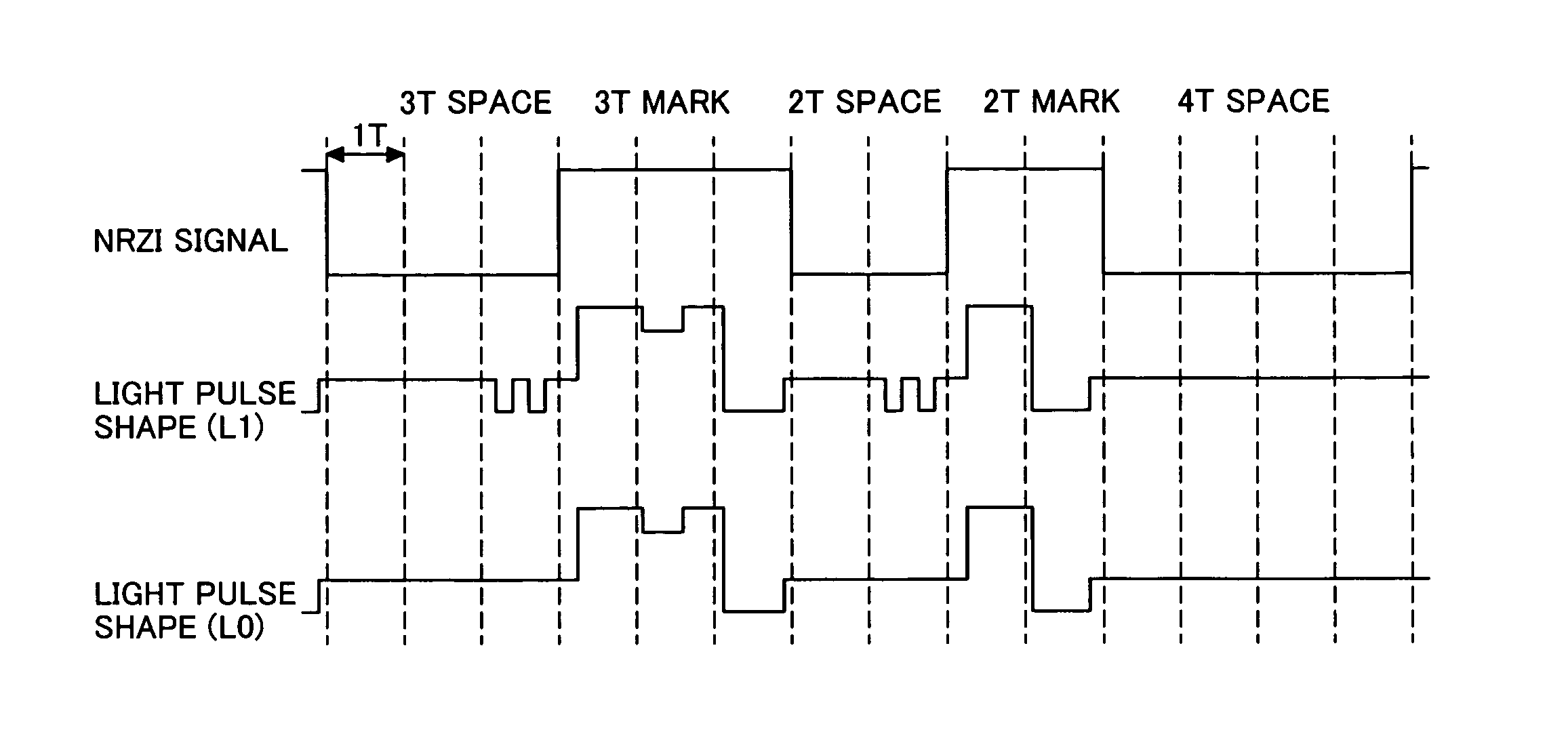
[0039] The recording method used in the present embodiment is explained. When data is written on an optical disc, the method of mark edge recording with a multipulse is used and the data is written on the disc as the information of the lengths of a mark and a space. Here, a modulation method wherein both the lengths of a mark and a space are the combination of the integer values in the range from 2T to 9T is used. FIG. 1 shows an example of a write strategy used in the present invention. As shown in FIG. 1, the feature of the write strategy used in the L1 layer recording is that: the laser beam waveform used for irradiation at the time of the forming of a space comprises the power of two levels; and the average irradiation energy at the back portion of the space is different from the average irradiation energy at the front portion of the space. As a result of examining the he...

second embodiment

[0051] In the present embodiment, a blue light source compatible disc B having an L1 layer the lamination structure of which was different from that of the blue light source compatible disc used in the first embodiment was prepared and random signals were recorded on the L1 layer. The L0 layer had the same lamination structure as the disc A used in the first embodiment and hence the details thereof are omitted here. As shown in (b) of FIG. 4, at the space having the length other than that of the 2T space, a non-pulse waveform having one power level was used and, only at the 2T space, a waveform having two power levels (Ps1 and Ps2) was employed. With regard to the laser power, the peak power (Pw) was 14.0 mW, the intermediate power (Ps1) 3.8 mW, and the bias power (Pb) 0.3 mW. The laser power Ps2 of the downward pulse was set at 0.65 mW, which was the same as the read power. Further, one pulse was set as the downward pulse and the pulse width W1 was set at 4 / 16T. For comparison, sig...

third embodiment

[0056] In the present embodiment, record reproduction was carried out using a blue light source compatible disc that had only one recording layer to store information and was capable of 6× recording. The linear velocity was set at 31.7 m / s. and a write waveform comprising 2T to 9T marks was used. The drive used was the same as the one used in the first embodiment. With regard to the laser power, the peak power (Pw) was 18.0 mW, the intermediate power (Ps1) 4.5 mW, the bias power (Pb) 0.1 mW, and the laser power (Ps2) of the downward pulse 0.1 mW, which was the same as the bias power, and the write strategy shown in (b) of FIG. 4 was used. In the present embodiment, the downward pulse was inserted only in the 2T space. One pulse was set as the downward pulse and the pulse width W1 was set at 3 / 16T. As a result of the record reproduction, the jitter was 4.9% and showed a practically usable good value. Here, the preferable position of the insertion of the downward pulse is a portion of...


PUM

PropertyMeasurementUnit
poweraaaaaaaaaa
wavelengthaaaaaaaaaa
linear velocityaaaaaaaaaa

Abstract

An information recording method of recording information with a high degree of accuracy on a semitransparent recording layer, which is subjected to severe thermal interference, of a multilayered recording medium. A downward pulse is applied to the back half portion of a prescribed space in the waveform of an energy beam used for irradiation when the space is formed. Thereby good recording performance is obtained.

Description

CLAIM OF PRIORITY [0001] The present application claims priority from Japanese application JP 2005-222329 filed on Aug. 1, 2005, the content of which is hereby incorporated by reference into this application. FIELD OF THE INVENTION [0002] The present invention relates to an information recording method and an information recording device for recording information by injecting energy into a recording medium and forming a mark different from a non-recording part. BACKGROUND OF THE INVENTION [0003] In recent years, the capacity of an optical disc increases conspicuously as an information amount to be handled increases. For example, whereas the capacity was 2.6 GB / face in the case of a DVD-RAM of the first generation, as a result of efforts for technology development such as shorter wavelength of a laser to be used and a higher NA of a lens, the capacity of 25 GB / face has been realized in the case of a blue-ray disc. Further, research and development in the technology of increasing an a...

Claims


Application Information

Patent Timeline
Patent Type & Authority Applications(United States)
IPC IPC(8): G11B7/0045
CPCG11B2007/0013G11B7/0062
Inventor USHIYAMA, JUNKO
Owner HITACHI CONSUMER ELECTRONICS CORP