Stator assembly, module and method for forming a rotary machine

a technology of rotary machines and parts, applied in the direction of machines/engines, mechanical apparatus, liquid fuel engines, etc., can solve the problems of reducing the aerodynamic efficiency of engines, and achieve the effect of promoting engine efficiency and facilitating manufactur

Active Publication Date: 2007-02-01
RTX CORP
View PDF7 Cites 94 Cited by
  • Summary
  • Abstract
  • Description
  • Claims
  • Application Information

AI Technical Summary

Benefits of technology

[0030] A principal advantage of the present invention is the engine efficiency which results from blocking the loss of cooling air from a coolable stator assembly of a rotary machine which results from forming a seal chamber and disposing a resilient seal member in the chamber. In one embodiment another advantage is the life-cycle cost of an assembly having a seal chamber and a resilient seal member associated with the ease of manufacture, repair and inspection of the assembly that results from use of a modular type subassembly containing the seal member. In particular, ease of manufacture is promoted by supporting the second structure from the first structure, disposing the seal member in the seal chamber and attaching the retainer member from the first structure to form the modular subassembly. In one detailed embodiment, an advantage is the durability of the seal retainer associated with the level of force it uses to resist the anti-rotation moment acting on the seal segment during a rub of a rotor blade. The force is lower with the anti-rotation projection or lug extending outwardly from the hook of the outer air seal segment to a larger diameter as compared to the moment arm that results from having the lug extend inwardly from the seal retainer to engage the outer air seal segment at a smaller diameter.
[0031] The resilient seal member is disposed in the seal chamber and urged axially by cooling air pressure against the support and the outer air seal members under operative conditions, the outer air seal assembly further including a circumferentially extending retainer member which is removably attached to the support for providing access to the seal chamber and which extends axially to bound the seal chamber for enclosing the seal member in the seal chamber, for locating the seal member under non-operative conditions, and for retaining the seal member radially against cooling air pressure under operative conditions.
[0032] The foregoing features and advantages of the present invention will become more apparent in light of the following

Problems solved by technology

These pins require the machining of appropriate openings to receive the pins, require installation in a location that is difficult to reach and to inspect, and, require the manufacture and maintenance of additional parts for the engine.
These leak paths decrease the aerodynamic efficiency of the engine because the engine expended work to compress the cooling air.

Method used


Image

  • Stator assembly, module and method for forming a rotary machine
  • Stator assembly, module and method for forming a rotary machine
  • Stator assembly, module and method for forming a rotary machine

Examples


Embodiment Construction

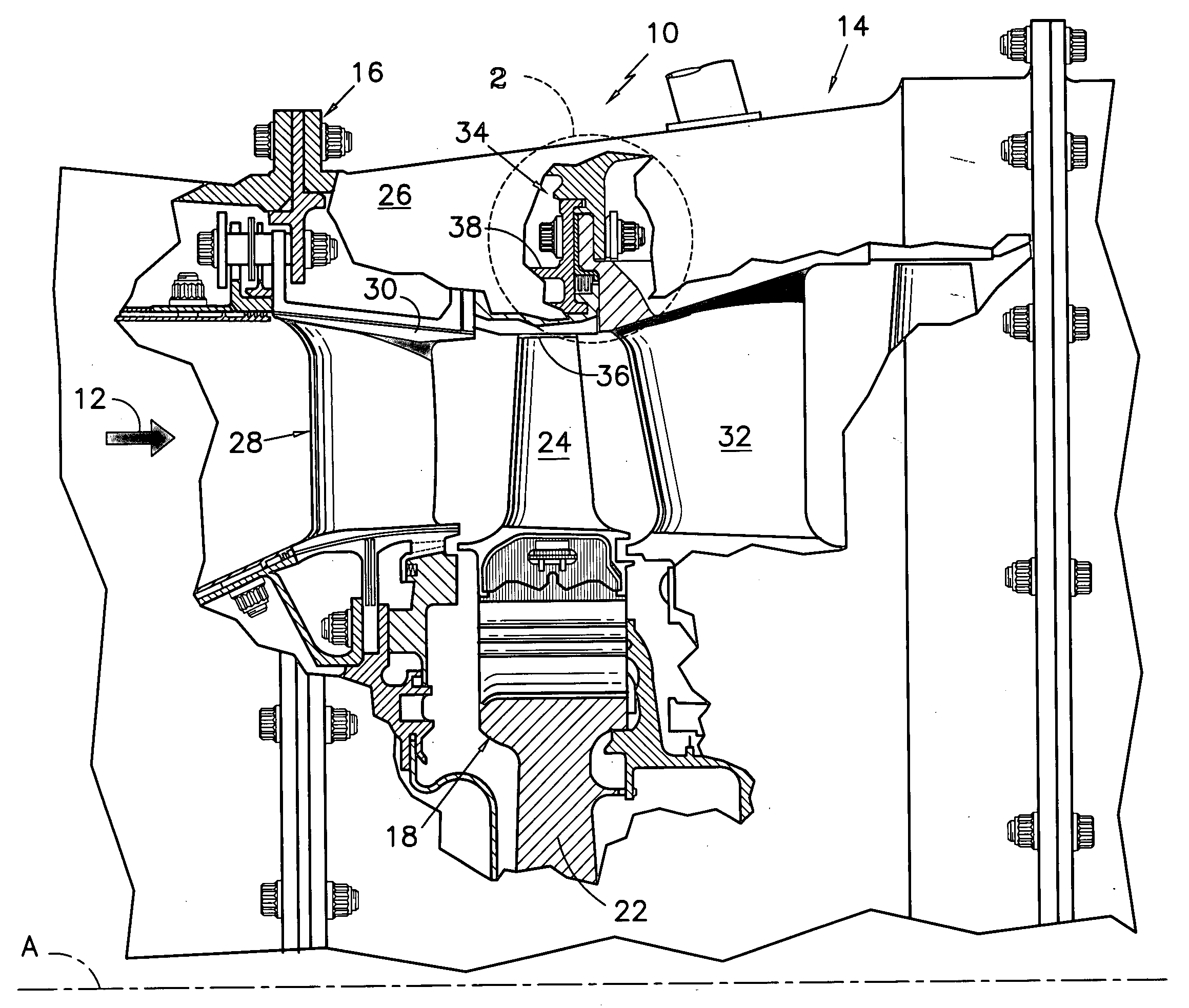
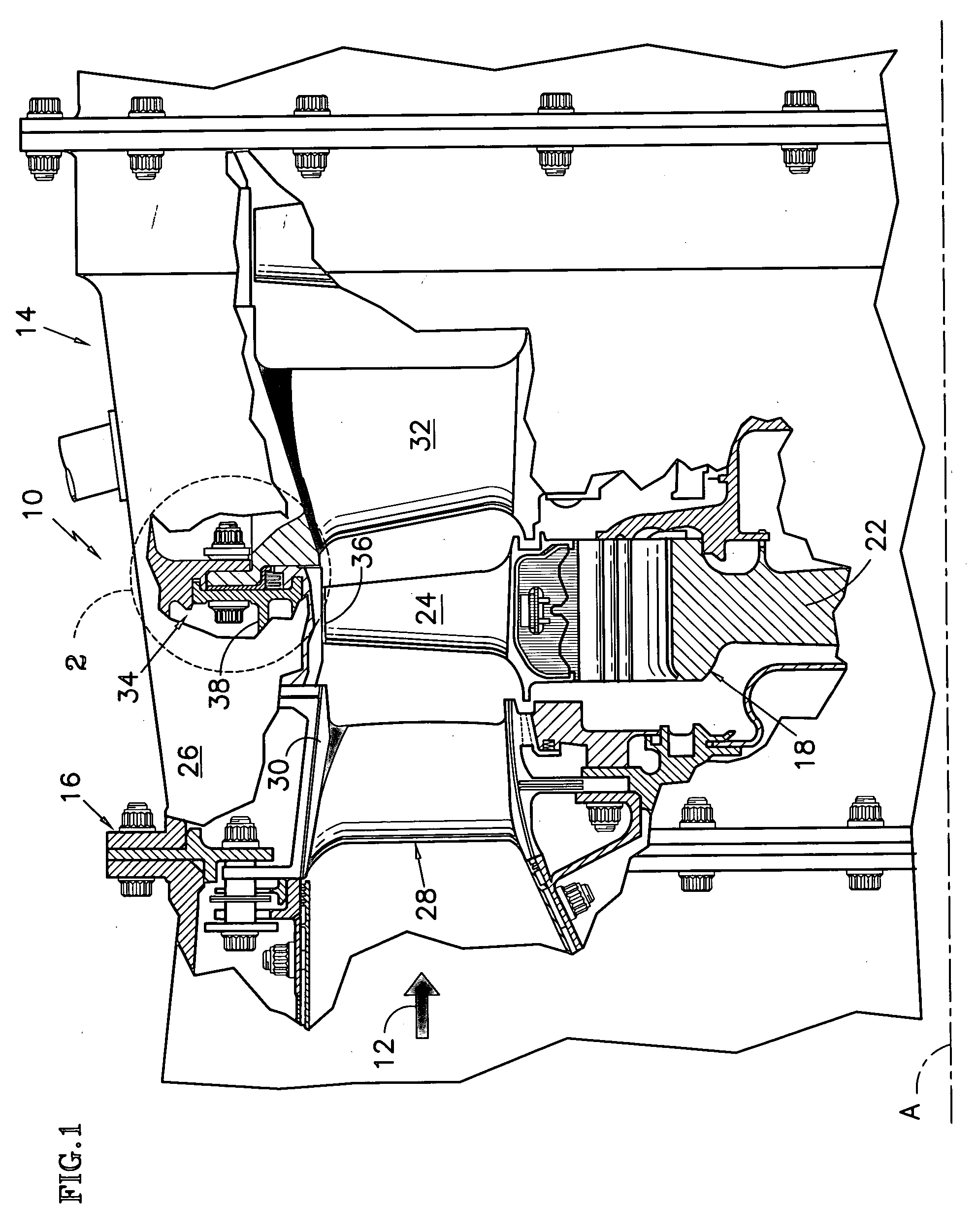
[0041]FIG. 1 is a side elevation view of a rotary machine, such as a gas turbine engine 10, having an axis of symmetry A. The engine 10 is partially broken away to show a cross-sectional view of the interior. The engine 10 has an annular flowpath 12 for working medium gases. The annular flowpath is disposed about the axis A and extends axially through the engine 10. The engine 10 includes a turbine section 14 having a stator assembly 16 and a rotor assembly 18 which each extend circumferentially with respect to the flowpath 12. The rotor assembly includes a rotor disk 22 and an array of rotor blades, as represented by the rotor blade 24. The rotor blades extend outwardly across the working medium flowpath into close proximity with the stator assembly.

[0042] The stator assembly 16 includes an outer case 26 and arrays of stator vanes 28, 32. The first array of stator vanes 28 extends inwardly from the outer case across the working medium flowpath 12. The first array of stator vanes a...


PUM


Abstract

A stator assembly for a rotary machine having an array of wall segments for bounding a working medium flow path is disclosed. Various construction details which provide a sealing structure for the segments are developed. In one detailed embodiment, a removable seal retainer for a seal chamber bounded by wall segments traps a resilient seal member in the seal chamber. In one particular embodiment, a modular subassembly for the engine is an outer air assembly disposed in a fixture as the subassembly is assembled.

Description

TECHNICAL FIELD [0001] This invention relates to axial flow rotary machines of the type having a flowpath for working medium gases and a stator structure extending circumferentially with respect to the working medium flow path. More particularly, this invention relates to a stator assembly having an array of wall segments that extend circumferentially for bounding the working medium flow path, such as an outer air seal or the platforms of an array of stator vanes. While this invention was conceived during work in the field of axial flow gas turbine engines, this invention has application to other fields which employ rotary machines. BACKGROUND OF THE INVENTION [0002] An axial flow, gas turbine engine typically has a compression section, a combustion section and a turbine section. An annular flowpath for working medium gases extends axially through the sections of the engine. A stator assembly extends inwardly and outwardly of and about the annular flowpath for confining the working ...

Claims


Application Information

Patent Timeline
Patent Type & Authority Applications(United States)
IPC IPC(8): F03B11/00
CPCF01D11/005F01D11/08F05D2240/57F05D2240/11F01D25/246
Inventor PEZZETTI, MICHAEL C. JR.FAUCHER, PETER A.KANE, DANIEL E.GOOD, RANDALL R.
Owner RTX CORP
Why Eureka
Try Eureka