
Spunbond facing and faced insulation assembly

a technology of facing and facing, applied in the direction of heat-proofing, identification means, instruments, etc., can solve the problems of mats slipping and shrinking away from hea

Inactive Publication Date: 2007-02-01
JOHNS MANVILLE CORP
View PDF4 Cites 9 Cited by
  • Summary
  • Abstract
  • Description
  • Claims
  • Application Information

AI Technical Summary

Benefits of technology

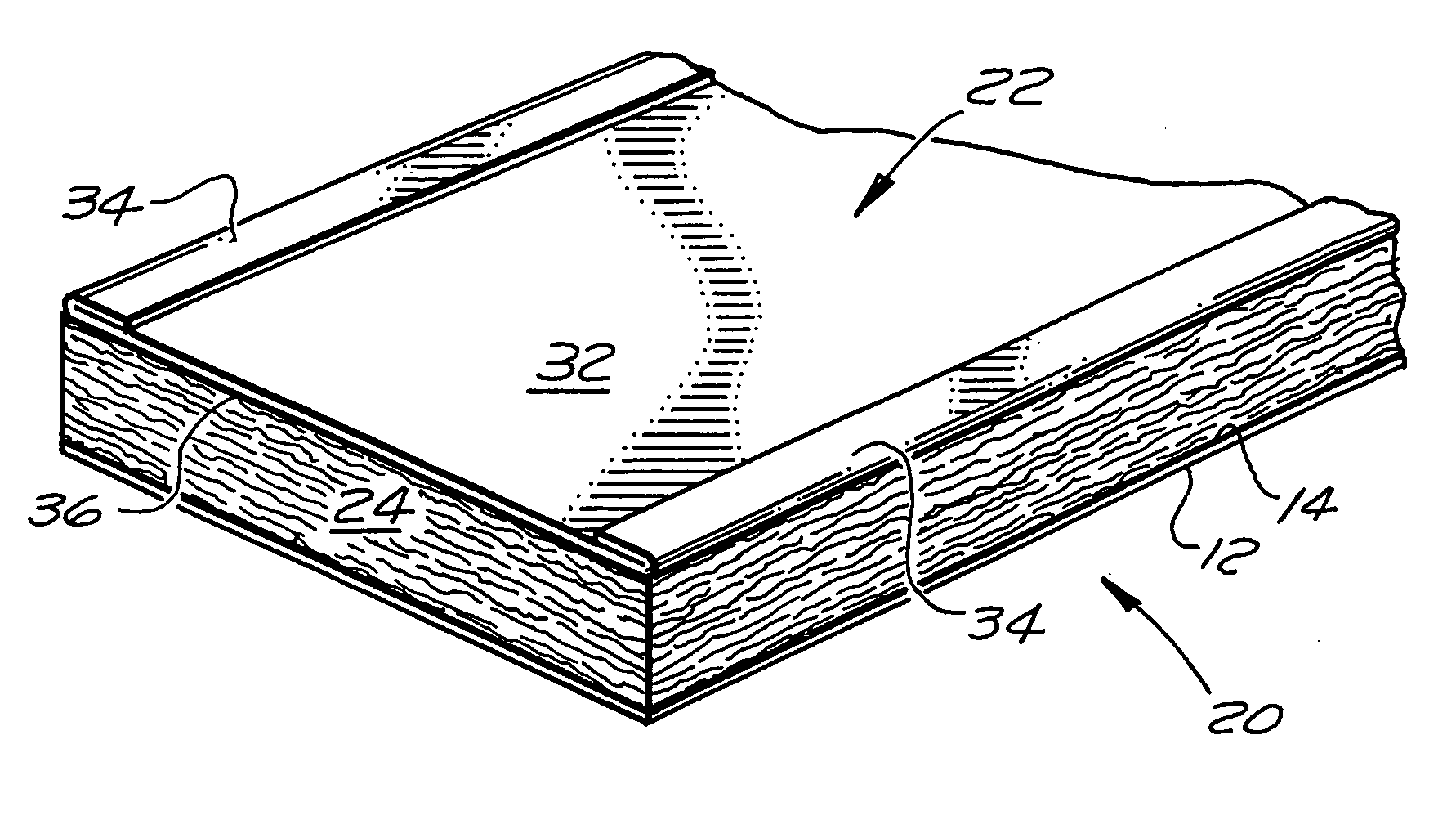
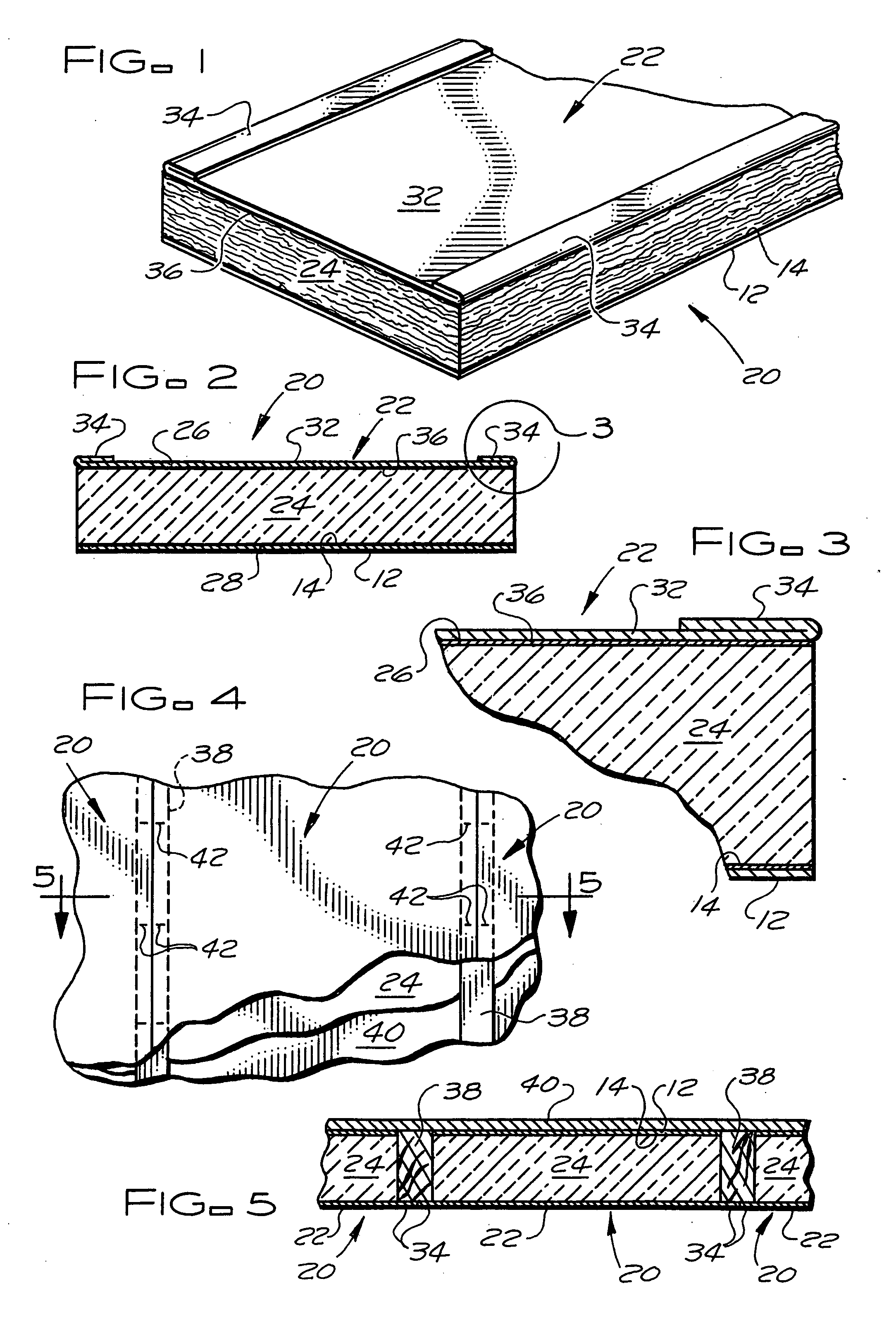
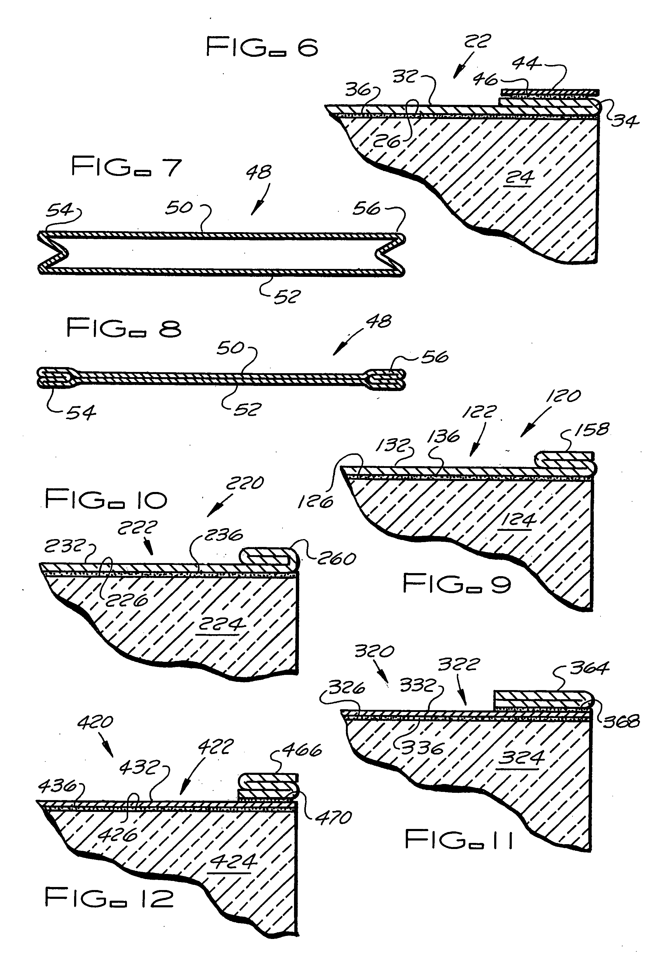
[0009] The facings of the subject invention may include a fungi-growth inhibiting agent, a pesticide, and / or may include a heat activated bonding layer that bonds the facing to the insulation layer of the assembly. As used herein the term “bonding layer” includes both a bonding layer that does not require heat activation such as but not limited to a coating, a spray on particulate, a spray on fiberized adhesive, or other continuous or discontinuous adhesive layers, and a heat activated bonding layer such as but not limited to asphalt, a polymeric film, a polymeric coating, a polymeric fiber mat, a polymeric fiber mesh, a spray on adhesive, a spray on particulate or fiberized adhesive, or other continuous or discontinuous heat activated adhesive layers having a softening point temperature sufficiently low to enable the heat activated adhesive layer to be heated to a temperature to effect a bond between the facing and a major surface of the insulation layer without degrading the facing. The bonding layer may be pre-applied to the facing or applied to the facing and / or major surface of the insulation layer at the point where the facing and the insulation layer are being combined.

Problems solved by technology

Such mats are difficult to ignite with a small ignition source and when exposed to a small flame, the mats tend to melt and shrink away from the heat long before the mats reach their ignition temperature.

Method used


Image

  • Spunbond facing and faced insulation assembly
  • Spunbond facing and faced insulation assembly
  • Spunbond facing and faced insulation assembly

Examples


embodiment 520

[0050]FIG. 13 shows an embodiment 520 of the faced insulation assembly of the subject invention wherein both the facing 522 and the insulation layer 524 are longitudinally separable to form faced insulation sections 572 having lesser widths than the faced insulation assembly 520. The insulation layer 524 has one or more longitudinally extending series of cuts and separable connectors, schematically represented by lines 574, which enable the insulation layer 524 to be pulled apart or separated by hand into the insulation sections 572 of lesser widths than the insulation layer 524. For each such series of cuts and separable connectors 574 in the insulation layer 524, the field portion 532 of the sheet 530 forming the facing 522 has a line of weakness 576 therein that is longitudinally aligned with the series of cuts and separable connectors so that the facing can also be separated or pulled apart by hand at each series of cuts and separable connectors. The line of weakness 576 may be ...

embodiment 620

[0051]FIGS. 14 and 15 show an embodiment 620 of the faced insulation assembly of the subject invention wherein both the facing 622 and the insulation layer 624 are longitudinally separable to form faced insulation sections 678 having lesser widths than the faced insulation assembly 624. The insulation layer 624 has one or more longitudinally extending series of cuts and separable connectors, schematically represented by lines 680, which enable the insulation layer 624 to be pulled apart or separated by hand into the insulation sections 678 of lesser widths than the insulation layer 624. For each such series of cuts and separable connectors 678 in the insulation layer 624, the field portion 632 of the sheet 630 forming the facing 622 has a fold 682 therein that is longitudinally aligned with the series of cuts and separable connectors. A separable pressure sensitive or other separable bonding adhesive 684 separably bonds the two segments of each fold 682 to each other and, typically,...

embodiment 820

[0053]FIGS. 19, 20 and 21 show an embodiment 820 of the faced insulation assembly of the subject invention wherein both the facing 822 and the insulation layer 824 are longitudinally separable to form faced insulation sections 890 having lesser widths than the faced insulation assembly 820. Like the faced insulation assembly 720 of FIGS. 16, 17 and 18, the facing of faced insulation assembly 820 does not have preformed tabs and the insulation layer 824 is made of a resilient insulation material, such as but not limited to a fiberglass insulation, that can be compressed in the direction of its width, e.g. laterally compressed an inch or more, and, after the compressive forces are released, will recover or substantially recover to its initial width. The insulation layer 824 has one or more longitudinally extending series of cuts and separable connectors, schematically represented by lines 892, which enable the insulation layer 824 to be pulled apart or separated by hand into the insul...


PUM


Abstract

A faced building insulation assembly includes a first facing forming a first major surface of the assembly with a central field portion having one or more spunbond continuous polymeric filament mat layers. Preferably, the facing is fungi growth resistant and has a selected water vapor permeance rating as applied to an insulation layer of the assembly. The facing may also include one or more polymeric film layers, a fungi growth inhibiting agent, a pesticide, and / or a heat activated bonding agent that bonds the facing to the insulation layer of the assembly. The insulation assembly may also include a second facing forming a second major surface of the assembly that has a water vapor permeance rating equal to or differing from the first facing.

Description

BACKGROUND OF THE INVENTION [0001] The subject invention relates to facings for faced building insulation assemblies, such as but not limited to those commonly used to insulate homes and other residential building structures; offices, stores, and other commercial building structures; and industrial building structures, and to the faced building insulation assemblies faced with such facings. The spunbond continuous polymeric filament mat facings of the subject invention, as applied to the insulation layers of the faced insulation assemblies of the subject invention, are designed to exhibit enhanced water vapor permeance characteristics for various applications. The spunbond continuous polymeric filament mat facings of the subject invention also exhibit enhanced handling characteristics, abrasion resistance, good dimensional stability, non-raveling edges, and excellent strength characteristics. The spunbond continuous polymeric filament mat facings of the subject invention also exhibi...

Claims


Application Information

Patent Timeline
Patent Type & Authority Applications(United States)
IPC IPC(8): G09F3/00E04B1/76E04B1/78
CPCE04B1/767E04B1/78Y10T428/15Y10T428/24322Y10T428/24231Y10T428/237
Inventor FAY, RALPH MICHAELBOGRETT, BLAKE BOYD
Owner JOHNS MANVILLE CORP
Learn More