Vapor feed fuel cell system with controllable fuel delivery

Inactive Publication Date: 2007-02-01
HIRSCH ROBERT S +5
View PDF18 Cites 10 Cited by
  • Summary
  • Abstract
  • Description
  • Claims
  • Application Information

AI Technical Summary

Benefits of technology

[0023] The adjustable fuel delivery regulation assembly of the present invention can be fabricated in one of a variety of alternative constructions. One aspect of the invention is embodied in a structure that includes two correspondingly perforated components that, in an open position, allow the flow of fuel through the perforations and when adjusted to a closed position, prevent flow of fuel because there are no openings through which fuel can flow. The adjustable structure also includes one or more intermediate positions in which smaller openings are provided through which a lesser amount of fuel flow is permitted in proportion to the size of the opening. These structures can be formed of slideable shutters that have apertures that are correspondingly located on each shutter component in such a manner that components can be positioned relative to one another such that the apertures can be aligned to allow fuel to flow through, or the apertures may be offset, to restrict the flow of fuel. Alternatively, the shutter components may be adjusted to an intermediate setting allowing adjustable control over the rate of fuel delivery.
[0025] In accordance with yet another embodiment of the invention, rotateable louvers or slotted cylinders are provided which when rotated to a first position close the regulator, thus restricting fuel from flowing. When the louvers or rods are rotated to a fully opened position, full fuel flow is permitted. Intermediate positions allow control of the amount of fuel that may flow to the anode aspect, which is typically in proportion to the size of the opening provided.
[0027] In yet another embodiment of the invention, a sheet of a non-permeable elastic material material, such as Latex or Nitrile, is provided with slits that open when the sheet is stretched, or otherwise placed under tension. This embodiment provides a solution in applications that may require a thinner component due to form factor, or other constraints. In accordance with another embodiment, a porous material that is compressible by an actuator or by gas pressure can be employed to regulate vapor flow.
[0028] Variable actuation of the adjustable fuel delivery regulation assembly can be provided by any one of a number of control systems as described herein. This control provides a means for maintaining optimal efficiency of the fuel cell over a range of operating conditions. It also facilitates a successful cold-start of the fuel cell.
[0030] A safety fastener can be included that will be engaged when the shutter is adjusted to its closed position. In addition, a seal upon the connections can also be provided to resist any leakage of fuel from the active fuel flow areas of the fuel cell system.

Problems solved by technology

In a vaporous feed fuel cell system, the fuel delivery regulation assembly limits vapor generation by limiting the amount of liquid that reaches the vapor delivery film.

Method used


Image

  • Vapor feed fuel cell system with controllable fuel delivery
  • Vapor feed fuel cell system with controllable fuel delivery
  • Vapor feed fuel cell system with controllable fuel delivery

Examples


example

[0070] An example of the operation of the fuel cell embodying the present invention will now be described for further illustration. An experiment was conducted to measure the variation in methanol flux (the amount of methanol delivered to the anode aspect of the fuel cell) as the shutter position is changed. The embodiment of the invention employed in the example was that illustrated in FIGS. 5A and 5B, with the rotatably mounted rods, which are also referred to in this Example as “dowels.”

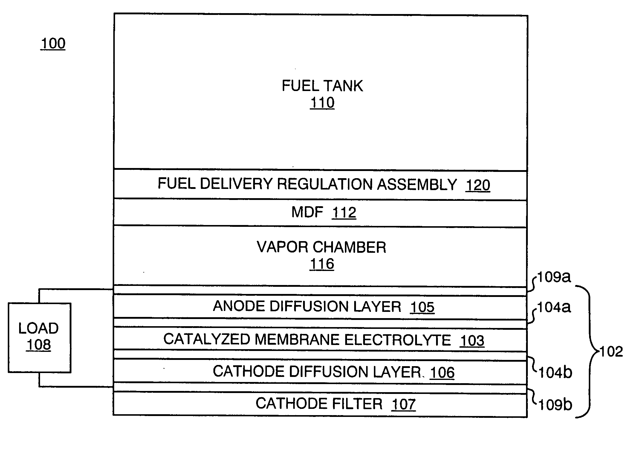
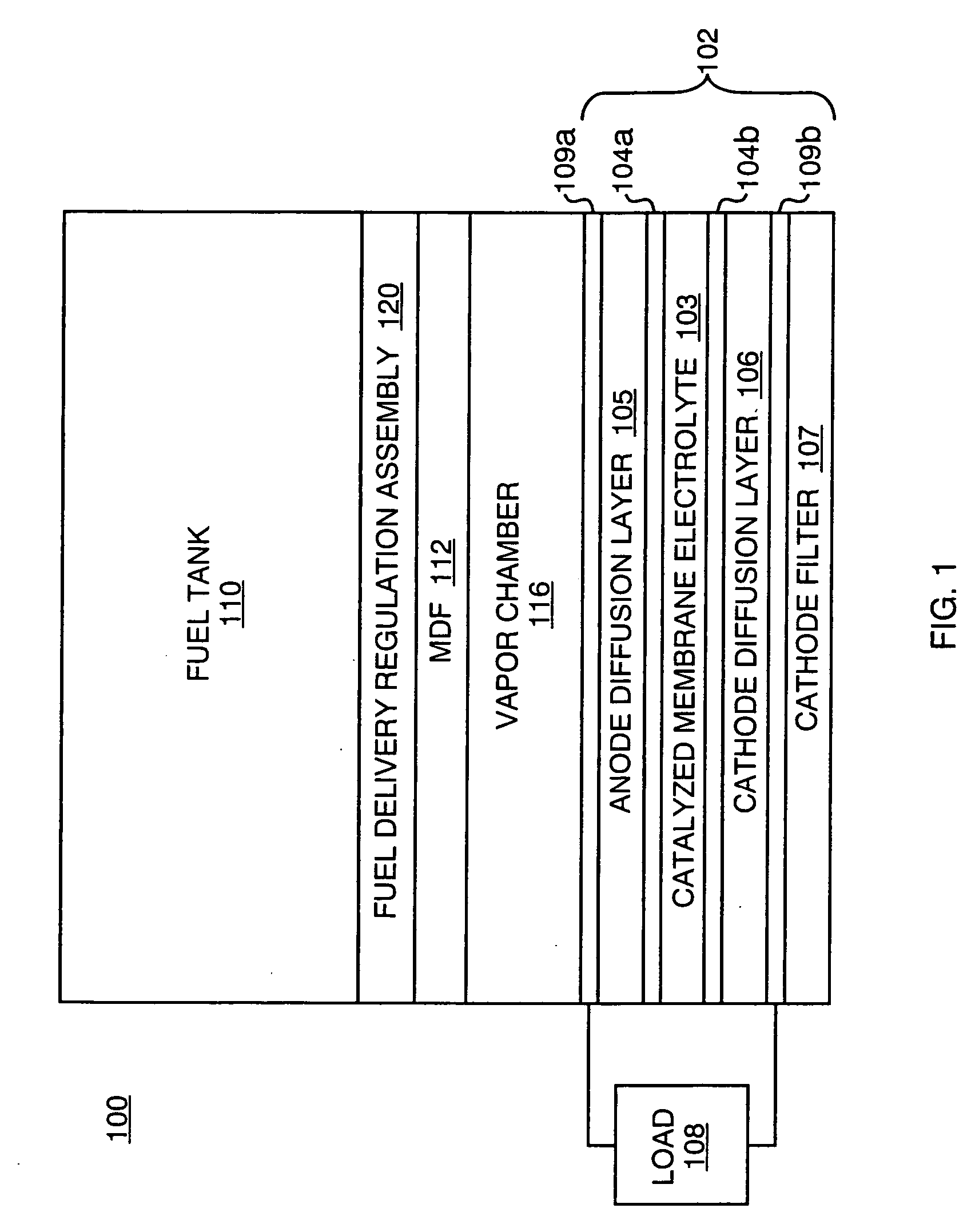
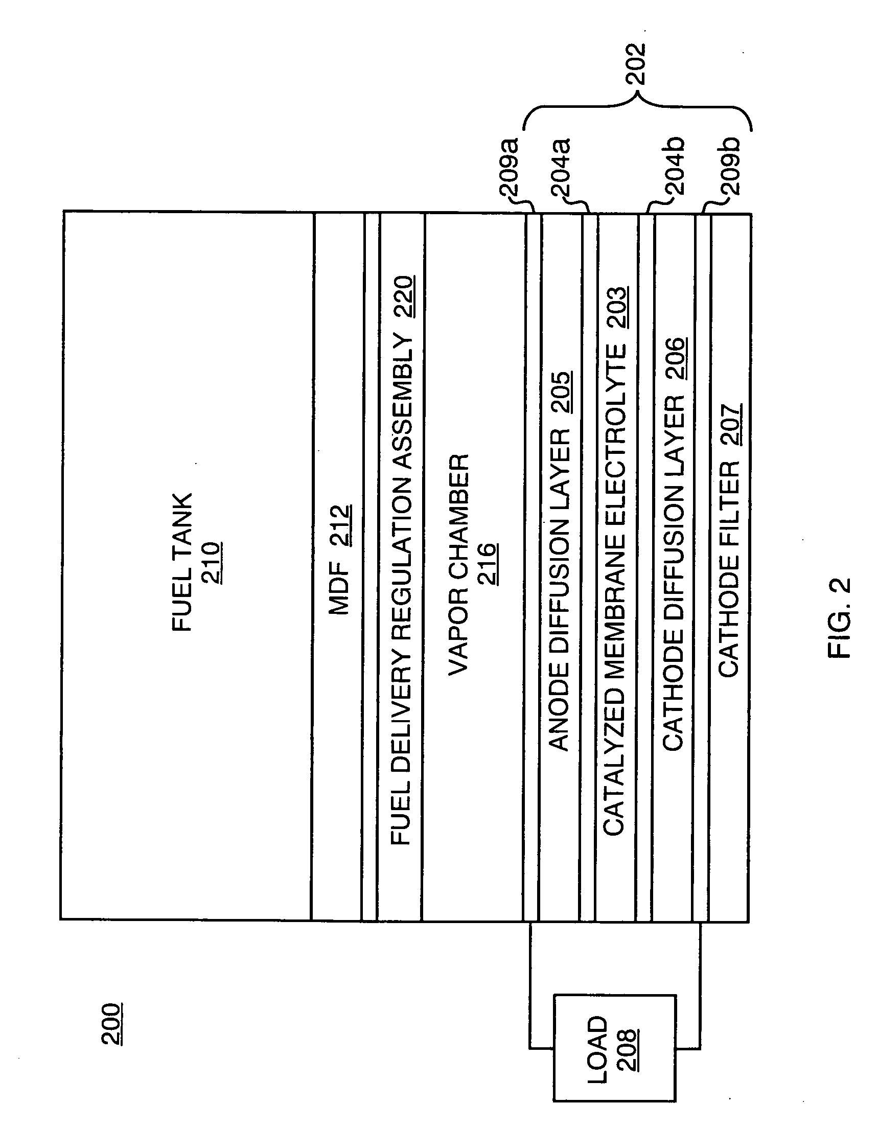
[0071] A single 5 cm2 DMFC was run in air-breathing mode with neat methanol vapor feed using an MDF as a mass transport layer with high methanol flux. In the test conducted, the fuel delivery regulation assembly was placed downstream of the MDF such that the shutter regulated fuel travelling from the MDF to the MEA (as illustrated in FIG. 2). The amount of MeOH reaching the MEA was controlled with the shutters. The cell current, (“Jcell”) at 0.3V and the limiting current (“Jlim”) (at 0.1-0.2V) was...


PUM

PropertyMeasurementUnit
thickaaaaaaaaaa
temperatureaaaaaaaaaa
currentaaaaaaaaaa

Abstract

An adjustable fuel delivery regulation assembly is provided which can be disposed within a direct oxidation fuel cell system, or the fuel reservoir or fuel tank that supplies such a system. One embodiment of the fuel delivery regulation assembly is a shutter assembly, which includes two correspondingly perforated components. The two components can be positioned relative to one another such that the apertures in each component are aligned in certain ways. In an open position, the apertures are substantially fully aligned to permit full fuel flow. In a closed position, the apertures are offset such that there is no opening; thereby fuel flow is restricted. Intermediate positions allow adjustments in the amount of fuel flow proportional to the size of the openings. In accordance with another embodiment of the invention, a set of rotatably mounted slotted rods is inserted into a housing through which fuel can flow through openings in the housing. When the rods are rotated to a first position, the slots in the rods are aligned with the openings in the housing. When the rods are rotated to a closed position, the slots are not lined up with the openings, and fuel flow is thereby restricted. Intermediate positions allow controlled fuel delivery. A louvered assembly is also provided. Automatic and manual control systems for the adjustment of the positioning of the various components in the fuel delivery regulation assemblies are also provided.

Description

BACKGROUND OF THE INVENTION [0001] 1. Field of the Invention [0002] This invention relates generally to direct oxidation fuel cells, and more particularly, to controlling fuel delivery within a fuel cell system. [0003] 2. Background Information [0004] Fuel cells are devices in which an electrochemical reaction involving a fuel molecule is used to generate electricity. A variety of compounds may be suited for use as a fuel depending upon the specific nature of the cell. Organic compounds, such as methanol or natural gas, are attractive fuel choices due to the their high specific energy. [0005] Fuel cell systems may be divided into “reformer-based” systems (i.e., those in which the fuel is processed in some fashion to extract hydrogen from the fuel before it is introduced into the fuel cell system) or “direct oxidation” systems in which the fuel is fed directly into the cell without the need for separate internal or external processing. Many currently developed fuel cells are reformer...

Claims


Application Information

Patent Timeline
Patent Type & Authority Applications(United States)
IPC IPC(8): H01M8/04H01M8/10
CPCH01M8/04089H01M8/04186H01M8/04201H01M8/04208Y02E60/50H01M8/1011H01M2008/1095Y02E60/523H01M8/0637H01M8/04H01M8/06
Inventor HIRSCH, ROBERT S.MUTOLO, PAUL F.BECERRA, JUAN J.SIEVERS, ROBERT K.SCARTOZZI, J. PERRYACKER, WILLIAM P.
Owner HIRSCH ROBERT S
Why Eureka
Try Eureka