Coalescing filter element with drainage mechanism

a filter element and drainage mechanism technology, which is applied in the direction of positive displacement liquid engine, auxillary pretreatment, separation process, etc., can solve the problem of reducing the area of the coalescer or filter unit that can be used to capture lubricant, and achieves the reduction of the pressure drop of compressed gas through the coalescing element, easy and cost-effective manufacturing, and increased media area

Active Publication Date: 2007-02-08
JOHNSON CONTROLS TYCO IP HLDG LLP
View PDF31 Cites 26 Cited by
  • Summary
  • Abstract
  • Description
  • Claims
  • Application Information

AI Technical Summary

Benefits of technology

[0013] One advantage of the present invention is that an increased amount of media area of the coalescing element is available to capture lubricant.
[0014] Another advantage of the present invention is that it can easily and cost-effectively be manufactured.
[0015] Still another advantage of the present invention is that the pressure drop of the compressed gas through the coalescing element is reduced.
[0016] A further advantage of the present invention is an increase in the limit on the velocity of compressed gas flowing through the coalescing element.
[0017] Other features and advantages of the present invention will be apparent from the following more detailed description of the preferred embodiment, taken in conjunction with the accompanying drawings which illustrate, by way of example, the principles of the invention.

Problems solved by technology

However, one problem with the use of the coalescer or filter unit is that the captured lubricant remains and accumulates in the coalescer or filter unit thereby reducing the amount of area of the coalescer or filter unit that can be used to capture lubricant.

Method used


Image

  • Coalescing filter element with drainage mechanism
  • Coalescing filter element with drainage mechanism
  • Coalescing filter element with drainage mechanism

Examples


Embodiment Construction

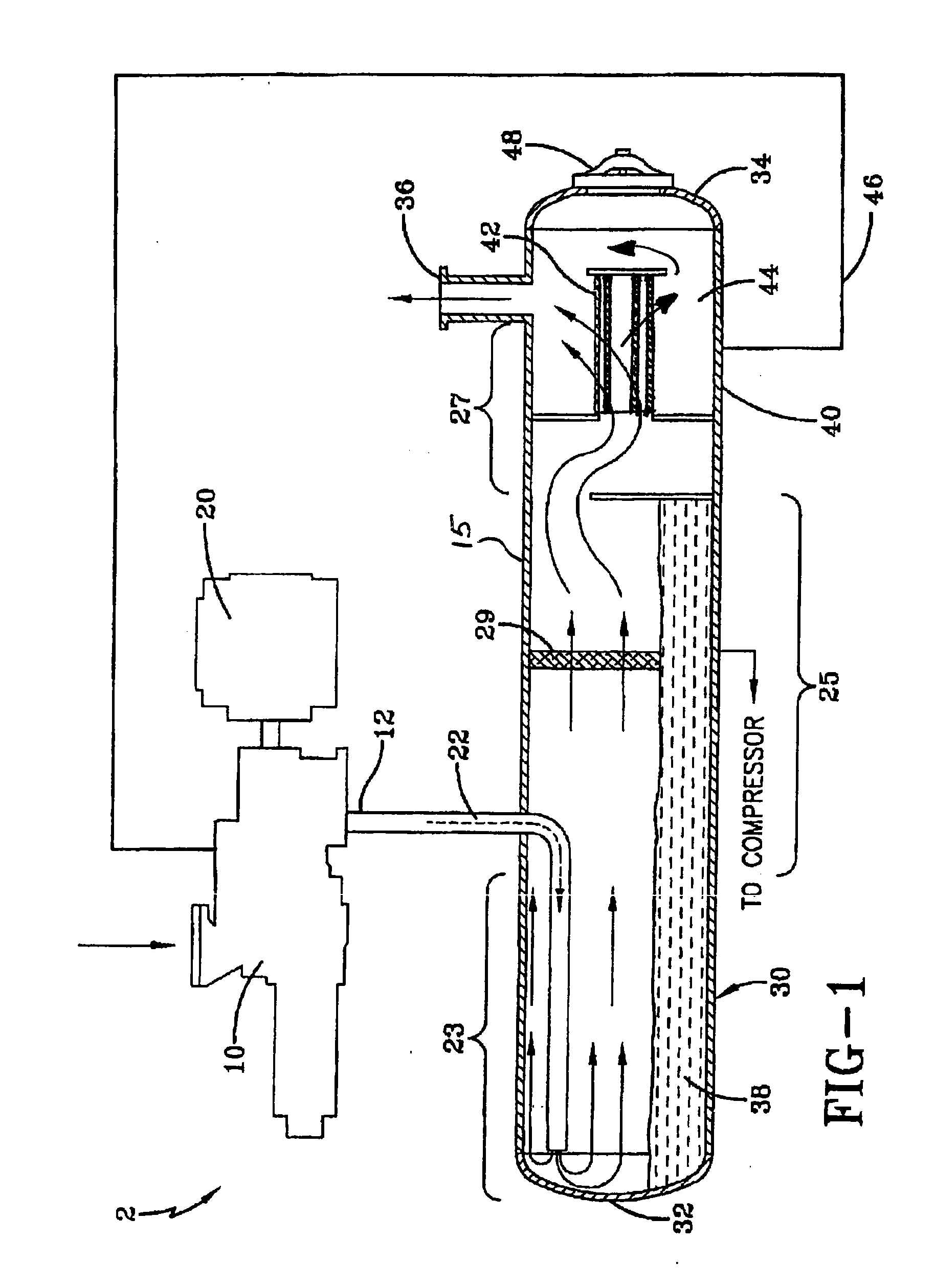
[0024]FIG. 1 illustrates an embodiment of a compression system that can incorporate the present invention. The compression system 2 includes a compressor 10, a motor 20, and a separator arrangement 30. The compressor 10 and motor 20 can be integrally mounted with the separator arrangement 30 or alternatively, the compressor 10, motor 20 and separator arrangement 30 can be separately mounted. The compressor 10 operates to compress a gas from a lower pressure to a higher pressure. The compressed gas can include entrained lubricant having a random size distribution. The droplet size of the lubricant can vary from greater than 1000 microns to submicron. The compressed gas and entrained lubricant exits the compressor 10 at a discharge port 12 where it is carried by conduit 22 into the separator arrangement 30.

[0025] In a preferred embodiment, the separator arrangement 30 is a horizontal separator in which the compressed fluid moves substantially axially (i.e., horizontally) through the ...


PUM

PropertyMeasurementUnit
droplet sizeaaaaaaaaaa
diameteraaaaaaaaaa
sizeaaaaaaaaaa

Abstract

The lubricant coalescing filter element is provided that includes a cylindrical outer screen member, at least one filter element disposed inside the cylindrical outer screen member and being coaxial with the outer screen member, and a drainage arrangement disposed between the cylindrical outer screen member and the at least one filter element to drain accumulated lubricant out of the at least one filter element.

Description

CROSS REFERENCE TO RELATED APPLICATIONS [0001] This application claims the benefit of U.S. Provisional Application No. 60 / 705,574 filed on Aug. 4, 2005, which Application is hereby incorporated by reference.BACKGROUND OF THE INVENTION [0002] The present invention relates generally to a coalescing filter element for a compression system. In particular, the present invention relates to an oil coalescing filter element having a drainage mechanism to reduce the amount of oil entrained in the filter media. [0003] Positive displacement compressors are machines in which successive volumes of air or gas are confined within a closed space and elevated to a higher pressure. The pressure of the gas is increased while the volume of the closed space is decreased. Positive displacement compressors include, for example, reciprocating compressors, rotary compressors, scroll compressors and screw compressors. These compressors rely on lubricating oil to lubricate rotating and contacting surfaces to ...

Claims


Application Information

Patent Timeline
Patent Type & Authority Applications(United States)
IPC IPC(8): B01D46/00
CPCB01D46/0024F04B39/02B01D46/2411B01D46/0031B01D46/64
Inventor BARRATT, THOMAS R.
Owner JOHNSON CONTROLS TYCO IP HLDG LLP
Why Eureka
Try Eureka