Composite structural element fabricating device and method

a technology of structural elements and fabricating devices, which is applied in auxillary welding devices, adhesive processes with surface pretreatment, paper hanging, etc., can solve the problems of composite material designs and unidirectional fibers not following the contour of structural members

Active Publication Date: 2007-02-08
THE BOEING CO
View PDF6 Cites 101 Cited by
  • Summary
  • Abstract
  • Description
  • Claims
  • Application Information

AI Technical Summary

Benefits of technology

[0101] The many features and advantages of the invention are apparent from the detailed specification, and thus, it is intended by the appended claims to cover all such features and advantages of the invention which fall within the true spirit and scope of the invention. Further, since numerous modifications and variations will readily occur to those skilled in the art, it is not desired to limit the invention to the exact construction and operation illustrated and described, and accordingly, all suitable modifications and equivalents may be resorted to, falling within the scope of the invention.

Problems solved by technology

However, the composite material designs can have the disadvantage that the unidirectional fibers do not follow the contour of the structural member.

Method used


Image

  • Composite structural element fabricating device and method
  • Composite structural element fabricating device and method
  • Composite structural element fabricating device and method

Examples


Embodiment Construction

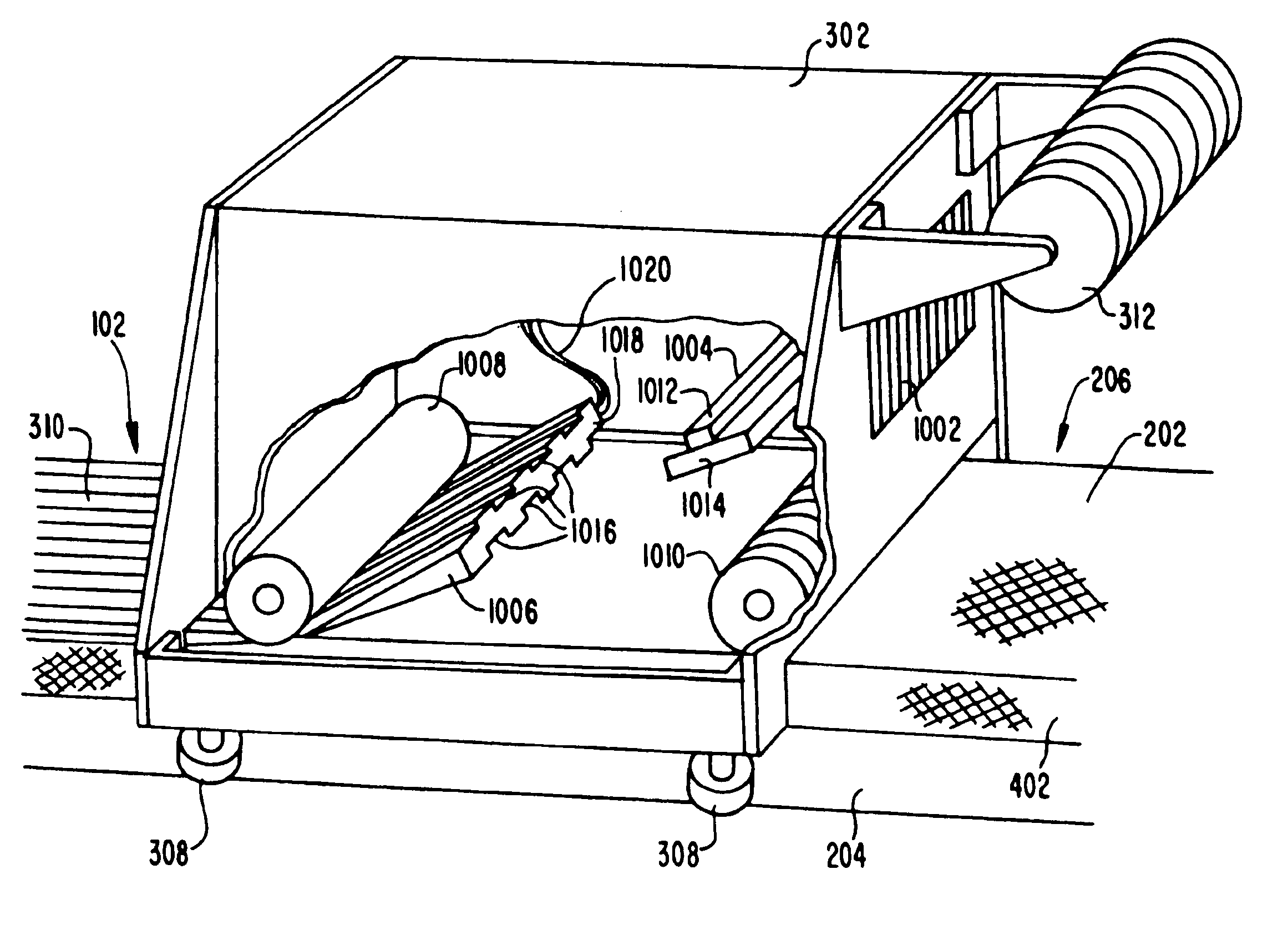
[0027] An embodiment in accordance with the present disclosure provides a device for manufacturing curved composite structural elements. The device is configured to place a ply on a form or manufacturing tool for a curved composite web such that the fiber orientation of the composite material is substantially aligned with the curvature of the structural element.

[0028] In addition or alternatively to placing a ply on the web, the device is configured to place a ply on the form or manufacturing tool for a curved composite flange or cap such that the fiber orientation of the composite material is substantially aligned with the centerline and / or edge of the structural element.

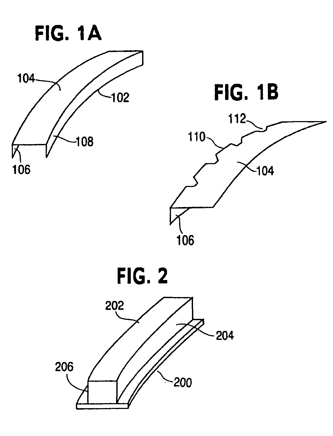
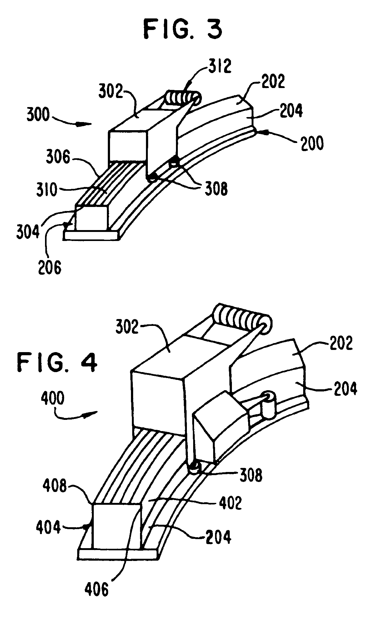
[0029] In the following disclosure, the composite structural element is first illustrated and described to give an example of a suitable context for an embodiment of the invention. However, other composite items are readily suitable for the various embodiments. For example, straight, compound curves, multi-axis c...


PUM

PropertyMeasurementUnit
widthsaaaaaaaaaa
widthsaaaaaaaaaa
angleaaaaaaaaaa

Abstract

To fabricate a composite item, a device places a composite ply on a curved form at about 0° relative to a longitudinal axis of the form. The form includes a web surface and a cap surface. The device includes a web compaction roller and a set of guides. The web compaction roller compacts a composite material upon the web surface and generate a web ply. The set of guide rollers urges against the cap surface. The compaction roller is directed along the form by the guide rollers.

Description

FIELD OF THE INVENTION [0001] The present disclosure relates generally to composite structures. More particularly, the present disclosure relates to a device and method of fabricating contoured structural elements from composite materials. BACKGROUND OF THE INVENTION [0002] Composite materials have been used increasingly in a variety of industries, including the automotive, marine and aerospace industries. Composite materials have been used to produce nonload-carrying structures, such as boat hulls or automobile body panels. Composite materials have also been applied in the manufacture of load-carrying structures, such as pressure vessels and aircraft fuselages. [0003] Composite materials especially have application in the design of load bearing structural members. Composite materials used in these designs include strong fibrous materials, such as carbon, aramid, glass or quartz, bonded together with a resin material, such as an epoxy. Such materials can have the advantage of a high...

Claims


Application Information

Patent Timeline
Patent Type & Authority Applications(United States)
IPC IPC(8): B32B37/00C09J5/02
CPCB29C70/38B29C70/545B29D99/0003Y10T156/1089B29C70/384Y10T156/1795B29L2031/003B29C70/34B29L2031/30
Inventor BROWN, TODD A.JONES, DARRELL D.MODIN, ANDREW E.
Owner THE BOEING CO
Why Eureka
Try Eureka