Heavy load carry slips and method

Inactive Publication Date: 2007-02-08
FORUM US
View PDF33 Cites 1 Cited by
  • Summary
  • Abstract
  • Description
  • Claims
  • Application Information

AI Technical Summary

Benefits of technology

[0028] An advantage of the present invention is that the new slip design ensures that the total weight of the string is distributed more evenly over the full vertical height of all the slip segments. Another advantage is that each insert is supported individually in the insert slot. This ensures that the loading forces are distributed away from the bottom of the slip, which is the thinnest section, and hence more susceptible to failure.
[0029] Another advantage is that the novel slip design will allow for longer slip lives. Yet another feature is that more weight can be suspended from the slips. For instance, the present design can be utilized in deep water drilling applications, since significant loads are created by the tubular work string. Still yet another advantage is that the inserts can be visually inspected when not in use for wear and fatigue. Yet another advantage is that the inserts can be easily replaced on the drill site.
[0030] An advantage of the second embodiment, which is the most preferred embodiment of this application, is that this embodiment allows for supporting a vertical load without generating an excessive transverse load that will crush the tubular being gripped at the rotary table. The transverse force that produces the gripping effect of the slips to hold the pipe from falling into the well is also the same force that crushes the pipe. Hence, if the pipe starts to crush, then the slips will also start to fail because of the improper loading. When this starts to happen, there is a domino effect that takes place and both problems are accelerated. Hence, an advantage is that the present invention prevents the crushing of the pipe which in turn slows down the deterioration of the slips. Yet another advantage is that the invention is designed specifically for the job of lowering heavy loads of casing, and other tubulars to the ocean floor, on the bottom of conventional drill pipe or landing strings.
[0031] A feature of the present invention is the angle machined into the ledge is complementary to the shoulder angle on the insert. Another feature is the gap between the individual longitudinal inserts in the event that an insert deforms longitudinally downward during use, the deformed insert will not press up against the adjacent insert. Another feature is that while rotary slips are shown, the invention is applicable to other slips such as, but not limited to, drill collar slips, casing slips and conductor slips.
[0032] Also, a feature of the invention herein disclosed is that the outer slip can have an angle greater than 11 degrees. Another feature is that the inner bowl will have an angle complementary of the outer slip. Yet another advantage is that the angle of the taper on the slip and bowl can vary from 11 to 15 degrees.

Problems solved by technology

Failure of a slip tends to manifest itself in bending or toeing outward of the bottom of the slip segments on this ledge, especially when the slips sit in a worn bowl since the slips are unsupported.
The equipment used with these deep water wells is large and extremely heavy.
As understood by those of ordinary skill in the art, the lifting and lowering capacity of the drilling rigs is being severely tested.
As the loads are increased, there is a danger of crushing the pipe, or alternatively, of slip failure.
However, with the use of landing strings in deepwater drilling and running long strings of casing down to the ocean floor on the bottom of a string of drill pipe, the crushing of the drill pipe, or alternatively, the slip failure has become an area of significant concern.
In the case of failure, the damage to the well could be catastrophic and could lead to dire consequences for the rig crew.

Method used


Image

  • Heavy load carry slips and method
  • Heavy load carry slips and method
  • Heavy load carry slips and method

Examples


Embodiment Construction

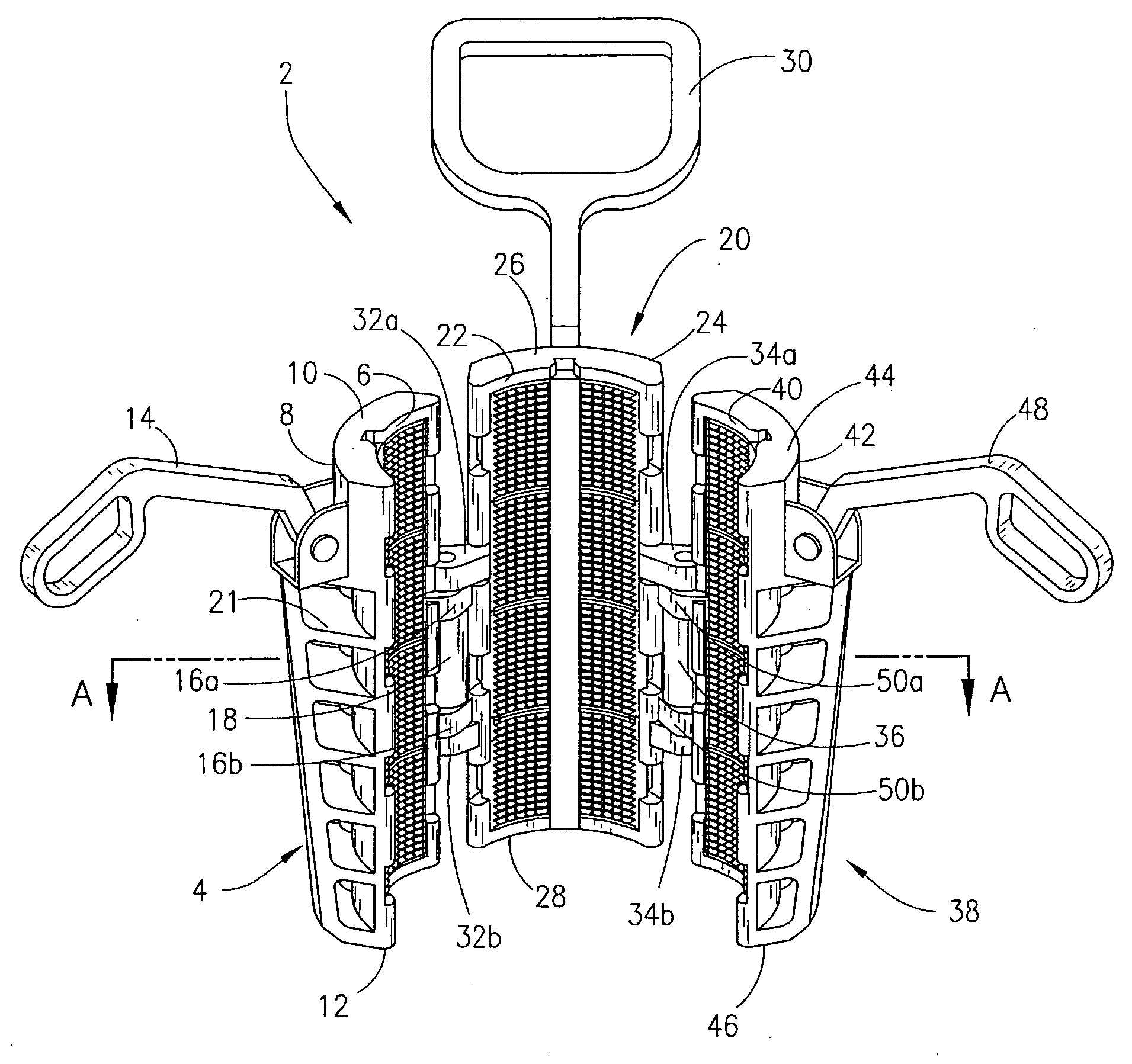
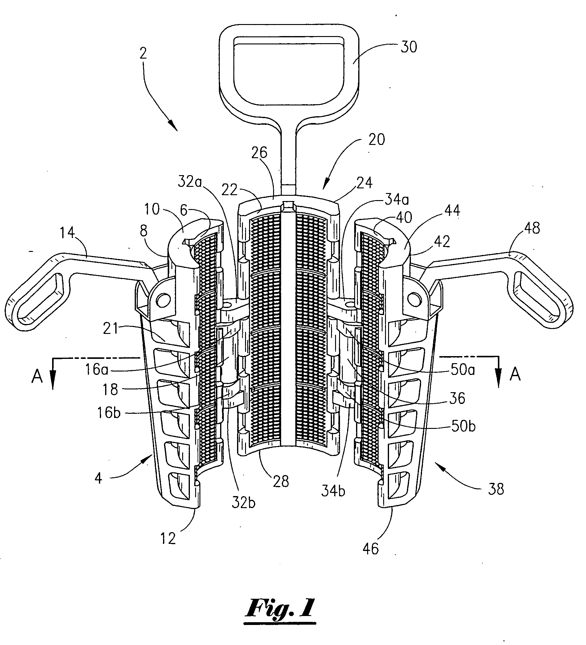
[0052] Referring now to FIG. 1, which is a perspective view of the assembled rotary slips, the preferred embodiment of the present invention will now be described. The rotary slips 2 are also sometimes referred to as a tubular handling device 2. The rotary slips 2 include a first slip 4, with the first slip 4 having a generally arcuate inner face 6 and a generally arcuate outer face 8. The slip 4 has a top end 10 and a bottom end 12. As seen in FIG. 1, the slip's profile is generally in a wedge shaped contour with the outer face 8 being tapered to the bottom end 12.

[0053] The slip 4 contains a handle member 14, with the handle member 14 being connected to the slip 4 with conventional means such as pins and cotters. Attachment means for attaching the slip 4 with the slip 20 includes the slip 4 containing a pair of projections 16a, 16b that have openings therein for placement of a hinge spring assembly 18 (which is also seen in FIG. 10) for connection with the second slip 20. The out...


PUM


Abstract

A tubular handling device. The device includes a plurality of slips, and wherein the slips have an arcuate inner face that has a longitudinally disposed slot and a ledge therein. The device further comprises an insert having a shoulder that is configured to fit within the ledge, and wherein the insert is capable of transferring a load from the shoulder to the ledge. In one preferred embodiment, the outer portion of the slips have a taper of greater than 11 degrees and a complementary bowl insert is provided that has a matching taper. A method of handling tubular members on a drilling rig is also disclosed.

Description

[0001] This application is a continuation in part of my presently pending patent application, bearing Ser. No. 10 / 198,542, filed on 16 Jul. 2002.BACKGROUND OF THE INVENTION [0002] This invention relates to a tubular handling device. More particularly, but not be way of limitation, this invention relates to a tubular slip device and method. [0003] In the drilling for oil and gas, the tubular members utilized during drilling, completion and work over operations are required to be hung off at the drill floor. The device generally used is referred to as a rotary slip. The prior art devices include an apparatus capable of encircling the tubular member. The apparatus has on its inner face slip means for gripping onto the tubular member. The apparatus is placed into a slip bowl on the drill rig floor, as is very well understood by those of ordinary skill in the art. Conventional rotary slips are commercially available from Access Oil Tools, Inc. of New Iberia, La. under the name “DU” and “...

Claims


Application Information

Patent Timeline
IPC IPC(8): E21B19/00B25B13/00B65H59/10E21BE21B19/10E21B29/10
CPCE21B19/10
Inventor RAMEY, JOE STEWARTLEBLANC, WILSON ANDREW JR.
Owner FORUM US
Why Eureka
Try Eureka