Piezoelectric position sensor for piezoelectrically driven resonant micromirrors

a piezoelectric position sensor and resonant micromirror technology, applied in the direction of instruments, optical elements, force/torque/work measurement apparatus, etc., can solve the problems of limited implementation, limited possibilities of detecting the position of resonantly driven or moved mems devices such as resonantly driven micromirrors, and the limitations of above mentioned measurement methods, etc., to achieve a large area

Active Publication Date: 2016-03-10
FRAUNHOFER GESELLSCHAFT ZUR FOERDERUNG DER ANGEWANDTEN FORSCHUNG EV
View PDF8 Cites 12 Cited by
  • Summary
  • Abstract
  • Description
  • Claims
  • Application Information

AI Technical Summary

Benefits of technology

[0018]Embodiments allow implementation of a monolithically producible position sensor for a piezoelectrically resonant micromirror, the sensor signal of which is suitable for controlling in a closed-loop control. For this purpose, conventional piezoresistive and capacitive measurement methods are—because of additional production steps—either not very attractive, comparatively insensitive (capacitive) or susceptible to failure (capacitive, piezoresistive). Conventional measurement methods based on metallic strain measuring strips may use, for the former, a sufficiently large area and a suitable design, while conventional measurement methods based on an optical process involve a comparatively expensive design which includes many components to be adjusted.

Problems solved by technology

Possibilities of detecting a position of resonantly driven or moved MEMS devices (MEMS=micro-electromechanical system), such as of resonantly driven micromirrors, are limited.
However, the above mentioned measurement methods have their specific limitations, as will be stated below.
This results in limited implementability [C. Zhang, G. Zhang, and Z. You, “A two-dimensional micro scanner integrated with a piezoelectric actuator and piezoresistors,” Sensors, vol.
In addition, piezoresistors made of a semiconductor material are sensitive also to light incidence and changes in temperature, which strongly limits the use of this class of sensors in a microdevice.
However, many MEMS designs lack suitable structures which on the one hand have large deformations and on the other hand provide sufficient space for a strain measuring strip [U. Baran, D. Brown, S. Holmstrom, D. Balma, W. O. Davis, P. Muralt, and H. Urey, “Resonant PZT MEMS Scanner for High-Resolution Displays,”J.
In such MEMS devices, the usage of strain measuring strips is therefore associated with poor sensitivity and poor resolution.
However, what is disadvantageous here are the comparatively low signal strengths and the interference of the signals by crosstalk.
Not least, the comparatively large electrode areas and their small distances cause significantly increased aerodynamic friction of the quickly moving micromirror, which is accompanied by a significant decrease in the maximum deflection of the resonant micromirror.
Here, however, an external light source, beam processing, and a detector (laser diode) may be used, which impair the compactness of a device [S. Richter, M. Stutz, A. Gratzke, Y. Schleitzer, G. Krampert, F. Hoeller, U. Wolf, L. Riedel, and D. Doering, “Position sensing and tracking with quasistatic MEMS mirrors,” 2013, p.
86160D], which eventually results in complex and expensive constructions.
For this purpose, conventional piezoresistive and capacitive measurement methods are—because of additional production steps—either not very attractive, comparatively insensitive (capacitive) or susceptible to failure (capacitive, piezoresistive).
Conventional measurement methods based on metallic strain measuring strips may use, for the former, a sufficiently large area and a suitable design, while conventional measurement methods based on an optical process involve a comparatively expensive design which includes many components to be adjusted.

Method used


Image

  • Piezoelectric position sensor for piezoelectrically driven resonant micromirrors
  • Piezoelectric position sensor for piezoelectrically driven resonant micromirrors
  • Piezoelectric position sensor for piezoelectrically driven resonant micromirrors

Examples


Embodiment Construction

[0034]In the following description of the embodiments of the invention, elements that are identical or have identical functions will be provided with the same reference numerals in the figures, such that their descriptions are interchangeable in the various embodiments.

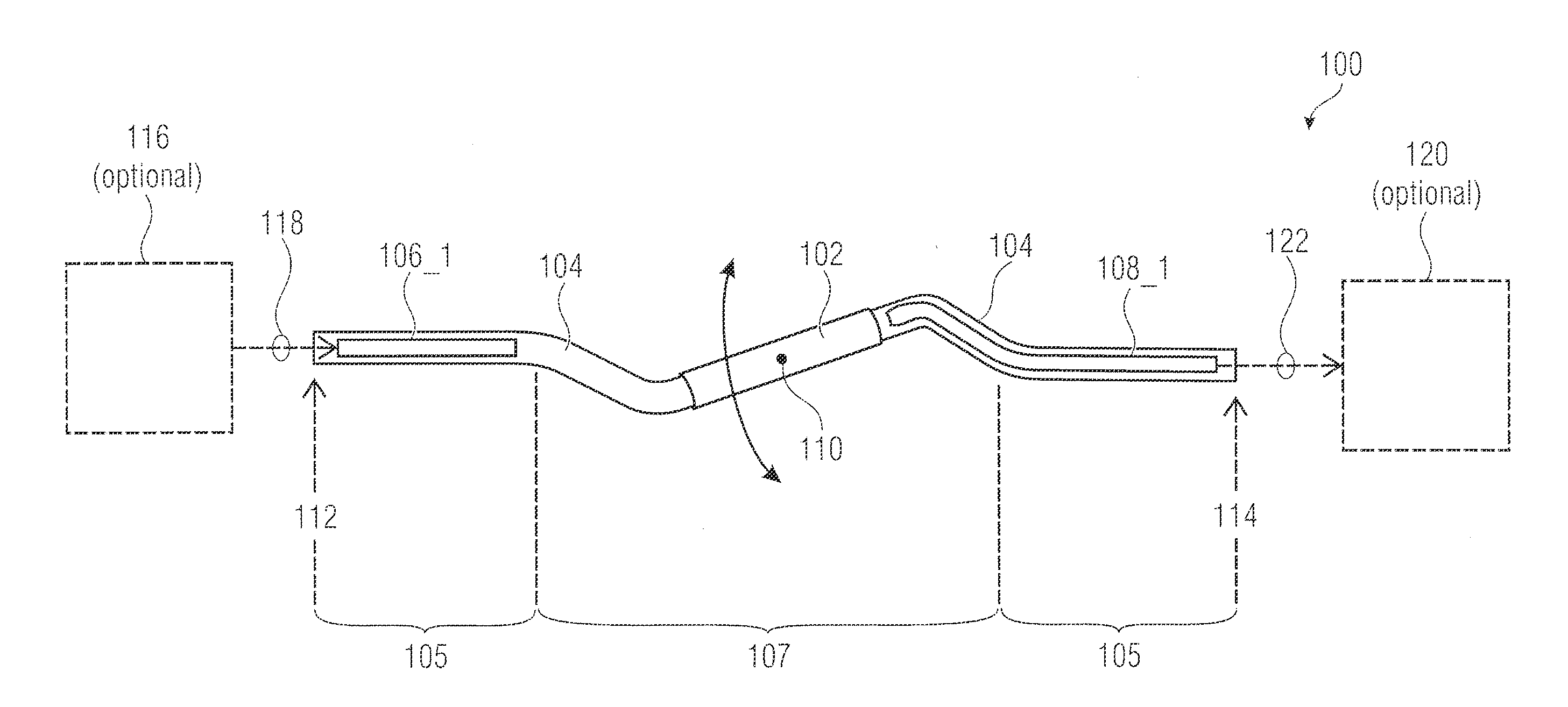
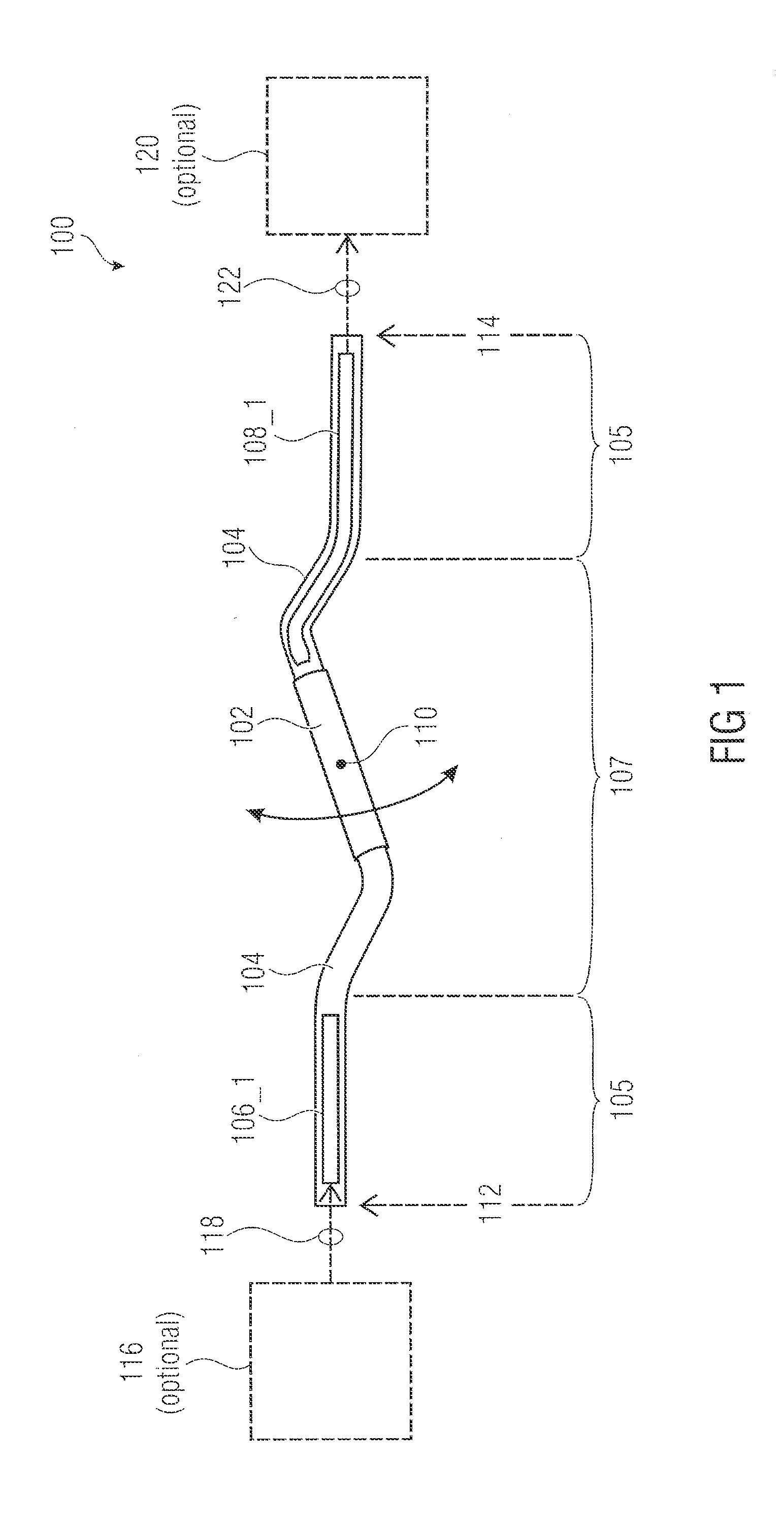
[0035]FIG. 1 shows an apparatus 100 for resonantly exciting a micromirror 102 and providing a sensor signal 122 dependent on a deflection of the micromirror 102. The apparatus 100 comprises an excitation structure 104 which contains, or supports, the micromirror 102 and comprises at least one piezoelectric actuator 106_1 to 106—n (n=1), the excitation structure 104 being configured to resonantly excite the micromirror 102 to cause a deflection (or oscillation or vibration) of the micromirror 102. In addition, the apparatus 100 comprises at least one piezoelectric sensor 108_1 to 108—m (m=1) for providing the sensor signal 122, the at least one piezoelectric sensor 108_1 to 108—m (m=1) being connected to the excitation...


PUM

PropertyMeasurementUnit
thicknessaaaaaaaaaa
thicknessaaaaaaaaaa
thicknessaaaaaaaaaa

Abstract

Embodiments of the present invention provide an apparatus including a micromirror, an excitation structure containing or supporting the micromirror, and at least one piezoelectric sensor. The excitation structure includes at least one piezoelectric actuator, the excitation structure being configured to resonantly excite the micromirror so as to cause a deflection of the micromirror. The at least one piezoelectric sensor is configured to provide a sensor signal dependent on the deflection of the micromirror, the piezoelectric sensor being connected to the excitation structure so that during the resonant excitation of the micromirror, the sensor signal and the deflection of the micromirror exhibit a fixed mutual phase relationship.

Description

CROSS-REFERENCE TO RELATED APPLICATIONS[0001]This application claims priority from German Patent Application No. 102014217799.5, which was filed on Sep. 5, 2014, and is incorporated herein in its entirety by reference.[0002]Embodiments of the present invention relate to an apparatus and a method for resonantly exciting a micromirror and for providing a sensor signal dependent on a deflection of the micromirror. Further embodiments relate to a method for producing such an apparatus. Some embodiments relate to a piezoelectric position sensor of piezoelectrically driven resonant micromirrors.BACKGROUND OF THE INVENTION[0003]Possibilities of detecting a position of resonantly driven or moved MEMS devices (MEMS=micro-electromechanical system), such as of resonantly driven micromirrors, are limited. Basically, one can detect either the movement of an actuator driving the micromirror or the movement of the micromirror directly. The most common sensor principles for position measurement of ...

Claims


Application Information

Patent Timeline
Patent Type & Authority Applications(United States)
IPC IPC(8): G01L1/16G01L5/00
CPCG01L5/00G01L1/167G02B26/0858H10N30/204B81B3/00
Inventor GU-STOPPEL, SHANSHANQUENZER, HANS-JOACHIMJANES, JOACHIMHEINRICH, FELIX
Owner FRAUNHOFER GESELLSCHAFT ZUR FOERDERUNG DER ANGEWANDTEN FORSCHUNG EV
Why Eureka
Try Eureka