Laser welding method and device

Inactive Publication Date: 2007-02-08
HONDA MOTOR CO LTD
View PDF6 Cites 1 Cited by
  • Summary
  • Abstract
  • Description
  • Claims
  • Application Information

AI Technical Summary

Benefits of technology

[0011] In the laser welding method, when electricity is supplied to the uppermost work in the works, via the electrode, the electrode contact portion of the work or the electrode contact portion and the heat transfer portion are thermally expanded and then contracted. Due to the foregoing, a deformed portion is formed. This deformed portion is separated from the adjoining work so as to form a gap between the works. At a position where an interval of the gap is large enough to spread the vapor generated by the vaporization of the coating heated, a laser beam is irradiated. The vapor, which is generated when the coating is heated, can be spread through the gap. Therefore, the works can be welded to each other without causing any defect. Consequently, according the laser welding met

Problems solved by technology

In general, in the case where flat works such as galvanized steel sheets, on the surfaces of which coating is provided, are overlapped with each other and welded by a laser beam, since a boiling point of zinc provided on the steel sheet surfaces is lower than a melting point of the sheet material, zinc is vaporized during the process of welding and zinc vapor is generated and the thus generated zinc vapor remains in the welding portion and further the thus generated zinc vapor blows out the melted steel sheet material, which could be a

Method used


Image

  • Laser welding method and device
  • Laser welding method and device
  • Laser welding method and device

Examples


Embodiment Construction

[0024] Exemplary embodiments of the invention will be described with reference to the accompanying drawings.

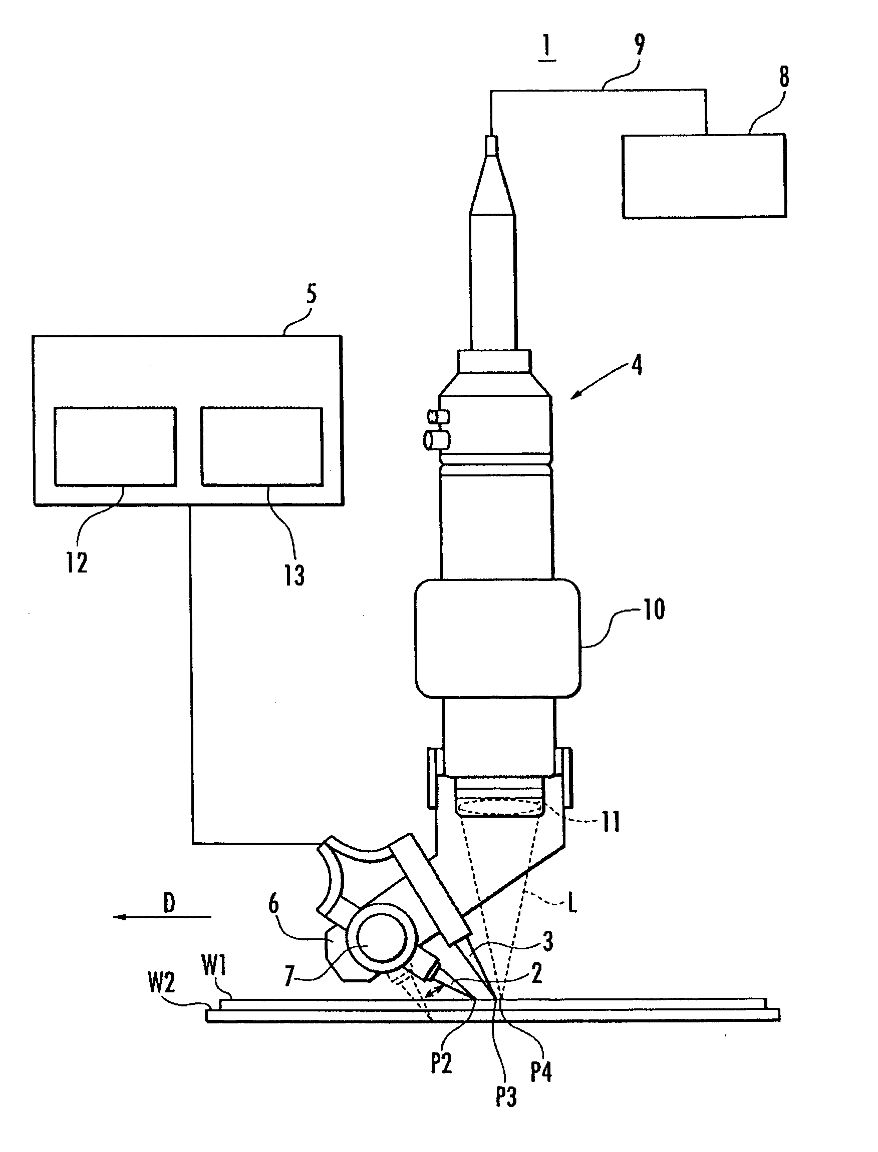
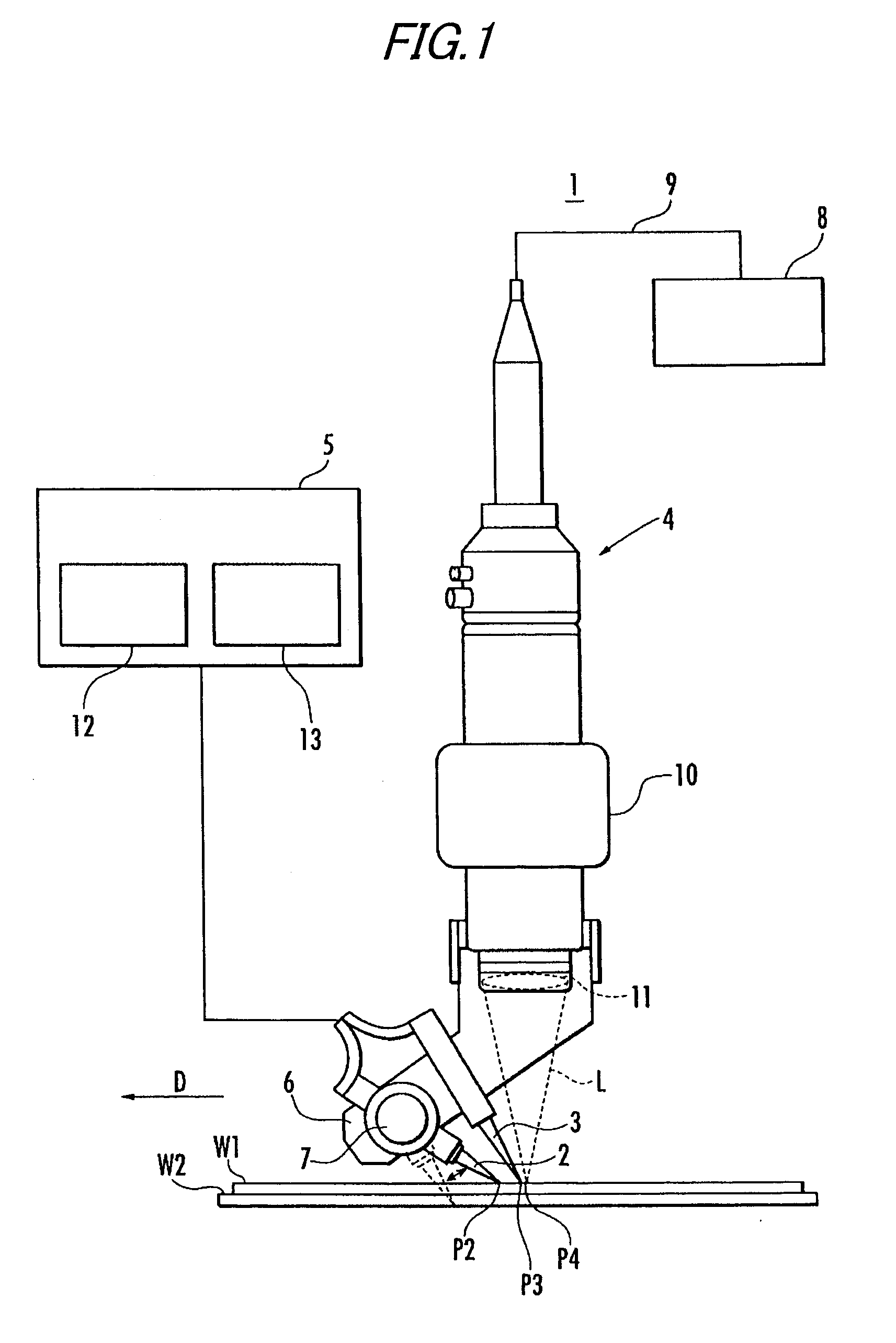
[0025]FIG. 1 is a schematic illustration for explaining a laser welding device to execute the laser welding method of a exemplary embodiment. FIG. 2 is a schematic illustration showing a positional relation on a steel sheet W1 of the present exemplary embodiment. FIGS. 3(a) to 3(c) are sectional views of the steel sheets W1 and W2 shown in FIG. 2. FIG. 4 is a schematic illustration showing a positional relation on the steel sheet W1 in another exemplary embodiment of the present invention. FIGS. 5(a) to 5(c) are sectional views of the steel sheets W1 and W2 shown in FIG. 4. FIG. 6 is a schematic illustration showing of still another exemplary embodiment of the present invention.

[0026] As shown in FIG. 1, the laser welding method of the present exemplary embodiment is a method of welding the galvanized steel sheets W1 and W2. The laser welding device 1 for executing the weldi...


PUM

PropertyMeasurementUnit
Pressureaaaaaaaaaa
Distanceaaaaaaaaaa

Abstract

Electrodes 2, 3 are contact with an uppermost work W1 and energized with electricity so as to thermally expand an electrode contact portion of the work W1 or alternatively so as to thermally expand the electrode contact portion of the work W1 and a heat transfer portion of an adjoining work W2 to which heat is transferred from the electrode contact portion, and then the portions are contracted so as to form a deformed portion Q and the deformed portion Q is separated from the adjoining works W1, W2 and a gap H is formed between the works W1, W2 which are overlapped, and a laser beam L is irradiated at a position where the gap H is large enough to spread the vapor generated by the vaporization of the coating heated.

Description

[0001] This application claims foreign priority from Japanese Patent Application No. 2005-228346, filed Aug. 5, 2005, the entire contents of which are hereby incorporated by reference. BACKGROUND OF THE INVENTION [0002] 1. Field of the Invention [0003] The present invention relates to a laser welding method of welding a plurality of flat works, which are overlapped with each other, having coating on the surfaces with a laser beam. The present invention also relates to a laser welding device to which the laser welding method is applied. [0004] 2. Related Art [0005] In general, in the case where flat works such as galvanized steel sheets, on the surfaces of which coating is provided, are overlapped with each other and welded by a laser beam, since a boiling point of zinc provided on the steel sheet surfaces is lower than a melting point of the sheet material, zinc is vaporized during the process of welding and zinc vapor is generated and the thus generated zinc vapor remains in the we...

Claims


Application Information

Patent Timeline
IPC IPC(8): B23K26/24
CPCB23K26/246B23K2201/34B23K26/3293B23K26/3206B23K26/32B23K26/244B23K2101/35B23K2103/08B23K2103/50
Inventor ODA, KOJI
Owner HONDA MOTOR CO LTD
Why Eureka
Try Eureka