A self-control valve for anti-failure high-temperature dusty gas
A self-control valve, anti-failure technology, applied in the valve's device for absorbing fluid energy, lift valve, valve details, etc., can solve problems such as aging of valve core sealing ring, valve jamming damage, affecting sealing performance, etc. Contact surface, prolong life, and enhance sealing effect
- Summary
- Abstract
- Description
- Claims
- Application Information
AI Technical Summary
Problems solved by technology
Method used
Image
Examples
Embodiment 1
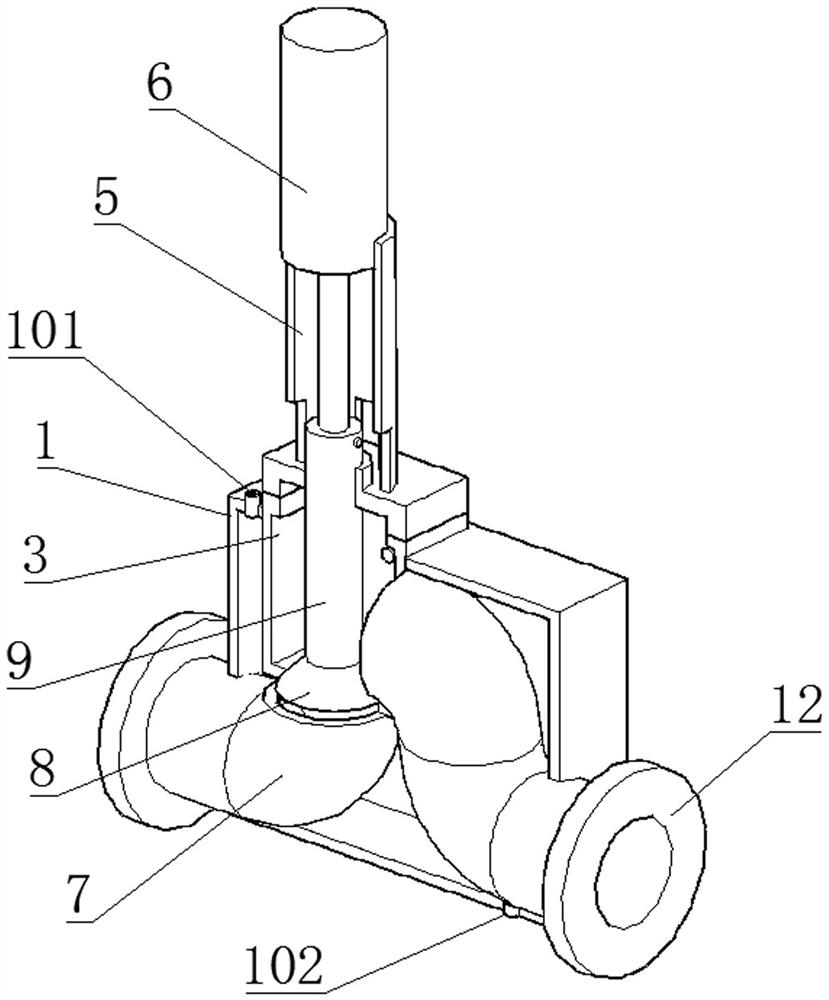
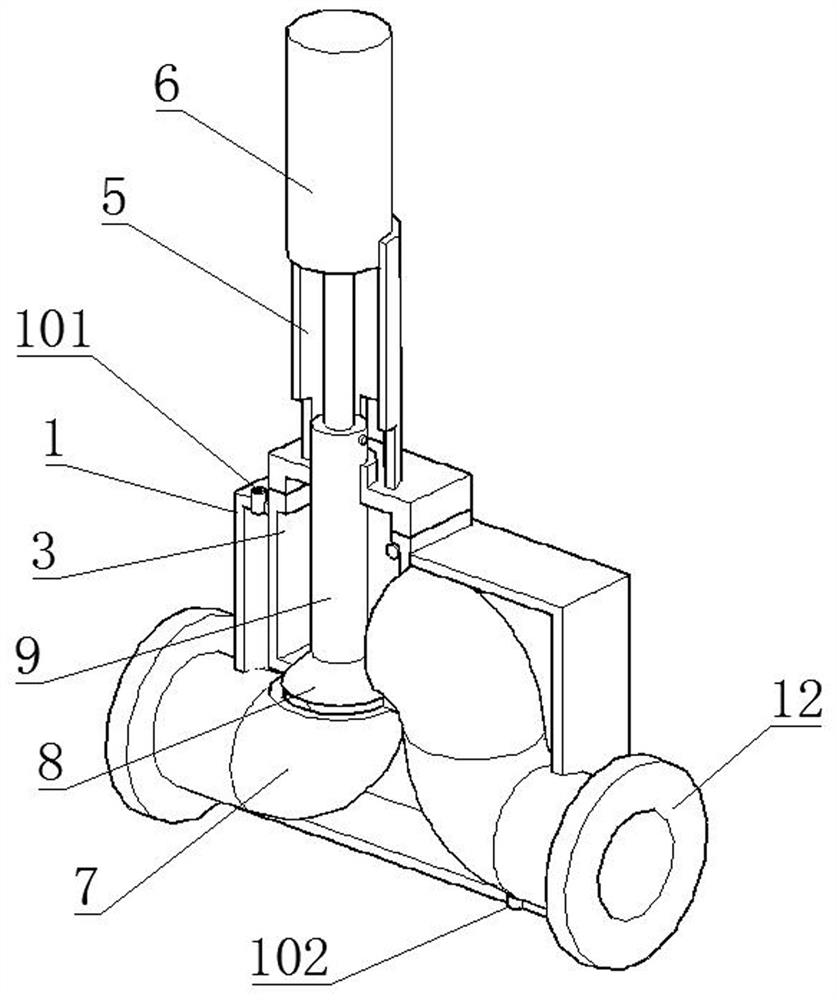
[0042] Such as Figure 1-2 As shown, a self-control valve for preventing failure of high-temperature dusty gas includes a cylinder 6, the cylinder 6 is fixed on the valve cover 4 through the bracket 5, and the piston rod of the cylinder 6 is fixedly connected with the valve rod 9 of the valve cover 4 passing through the valve cover 4. , the bonnet 4 is fixedly connected with the valve body 3, the end of the valve stem 9 located in the valve body 3 is fixedly connected with the valve core 8, the valve stem 9 and the valve core 8 are provided with a through passage, and the outside of the valve body 3 is fixedly connected with water tank 1.
[0043] The cylinder 6 connects the valve stem 9 and the valve core 8, and the movement of the valve stem 9 and the valve core 8 is controlled by the movement of the cylinder 6, so that the valve core 8 moves in the valve body 3 to realize the opening or closing of the valve body 3. The water tank 1 and the flow channel are arranged on the ...
Embodiment 2
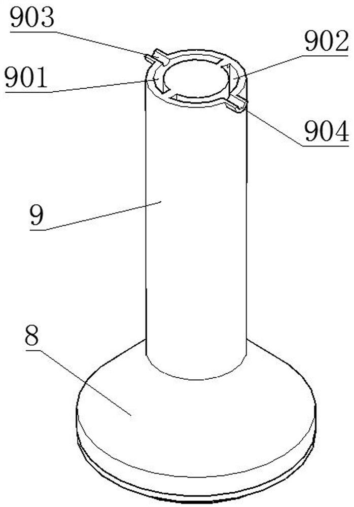
[0045] Such as Figure 1-4 As shown, a self-control valve for preventing failure of high-temperature dusty gas includes a cylinder 6, the cylinder 6 is fixed on the valve cover 4 through the bracket 5, and the piston rod of the cylinder 6 is fixedly connected with the valve rod 9 of the valve cover 4 passing through the valve cover 4. , the bonnet 4 is fixedly connected with the valve body 3, the end of the valve stem 9 located in the valve body 3 is fixedly connected with the valve core 8, the valve stem 9 and the valve core 8 are provided with a through passage, and the outside of the valve body 3 is fixedly connected with The water tank 1, the flow path includes an inflow groove 901 connected to the inlet port 903 on the side of the valve stem 9, the bottom end of the inflow groove 901 is located inside the valve core 8 and communicates with the return groove 902, the top of the return groove 902 communicates with the return port 904, the inflow groove 901, The cross sectio...
Embodiment 3
[0048] Such as Figure 1-8 As shown, a self-control valve for preventing failure of high-temperature dusty gas includes a cylinder 6, the cylinder 6 is fixed on the valve cover 4 through the bracket 5, and the piston rod of the cylinder 6 is fixedly connected with the valve rod 9 of the valve cover 4 passing through the valve cover 4. , the bonnet 4 is fixedly connected with the valve body 3, the end of the valve stem 9 located in the valve body 3 is fixedly connected with the valve core 8, the valve stem 9 and the valve core 8 are provided with a through passage, and the outside of the valve body 3 is fixedly connected with In the water tank 1, the valve body 3 is provided with a rotating plate 11 that is rotationally connected to the valve body 3 through a shaft 301. The rotating plate 11 is slidingly connected to the edge of the valve core 8. The upper surface of the rotating plate 11 is attached to the upper inner wall of the valve body 3. The top of the rotating plate 11 ...
PUM
 Abstract
Description
Claims
Application Information
 - R&D
- Intellectual Property
- Life Sciences
- Materials
- Tech Scout
- Unparalleled Data Quality
- Higher Quality Content
- 60% Fewer Hallucinations
Browse by: Latest US Patents, China's latest patents, Technical Efficacy Thesaurus, Application Domain, Technology Topic, Popular Technical Reports.
© 2025 PatSnap. All rights reserved.Legal|Privacy policy|Modern Slavery Act Transparency Statement|Sitemap|About US| Contact US: help@patsnap.com


